Automatic braking force regulating device for screw oil pump

An automatic adjustment and oil well pump technology, which is applied in pump control, pump components, machines/engines, etc., can solve the problems of poor safety and accidents of oil well operators, and achieve the effect of reducing the degree of danger, improving efficiency, and ensuring safety

Inactive Publication Date: 2014-12-10
BEIJING SHITONG HUAAO OILFIELD CHEM TECH
View PDF6 Cites 0 Cited by
  • Summary
  • Abstract
  • Description
  • Claims
  • Application Information

AI Technical Summary

Problems solved by technology

[0003] The purpose of the present invention is to provide an automatic adjustment device for the braking force of the screw oil well pump to solve the problem of accidents caused by parts on the ground driving equipment being thrown out at high speed when the screw oil pump is shut down or stuck in operation during the existing oilfield exploitation process. and issues leading to poor well worker safety

Method used


Image

  • Automatic braking force regulating device for screw oil pump
  • Automatic braking force regulating device for screw oil pump

Examples


specific Embodiment approach 1

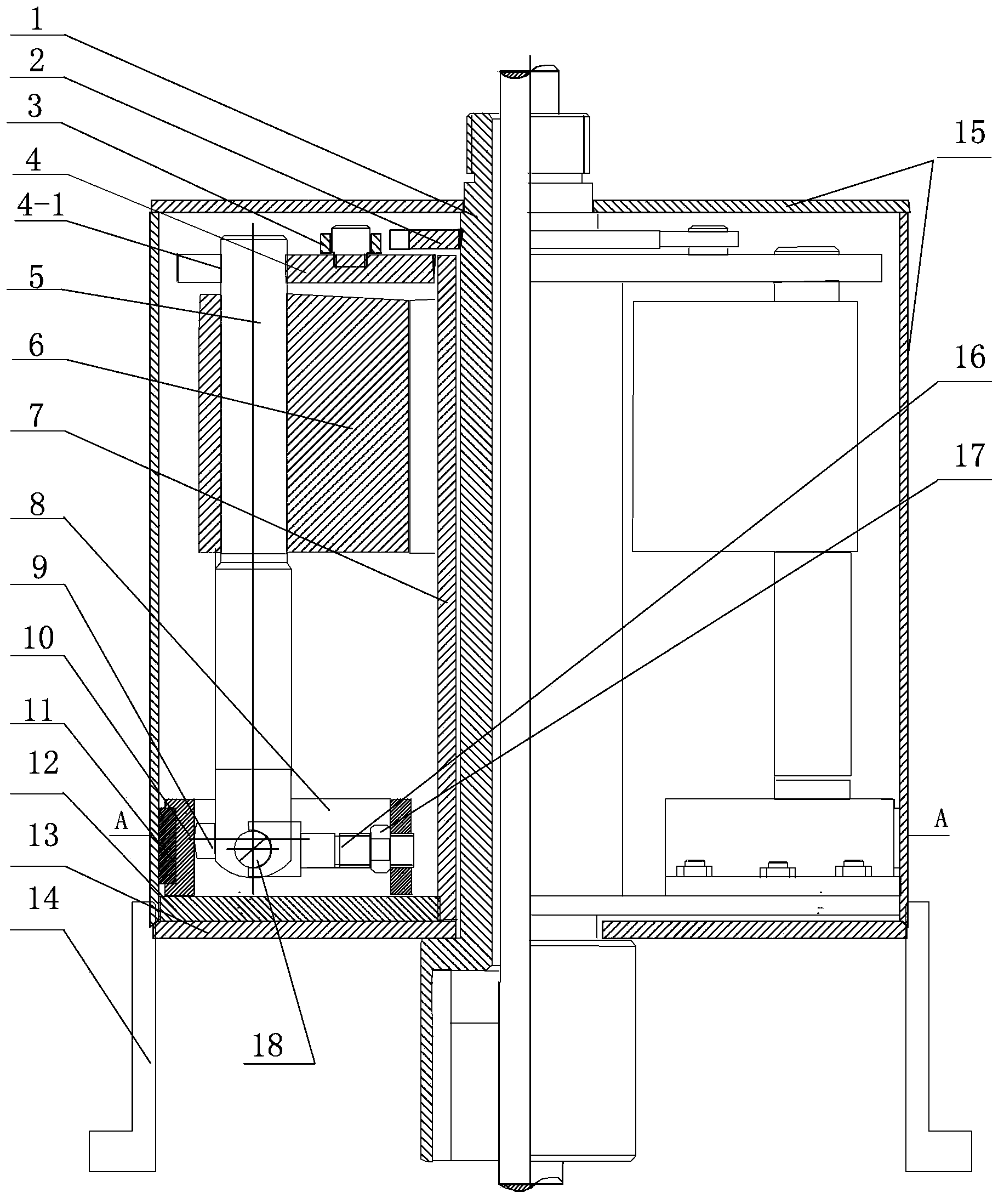
[0007] Specific implementation mode 1: Combination figure 1 To explain this embodiment, the device of this embodiment includes a branch pipe 1, a ratchet tooth 2, a pawl 3, a brake disc 4, a brake disc connecting pipe 7, a brake chassis 12, a base 13, a housing 15, and a rotating pin 18. , Two levers 5, two counterweights 6, two multifunctional brackets 8, two special-shaped cams 9, two friction plate fixing frames 10 and two friction plates 11, the bottom of the housing 15 is fixedly connected to the base 13 , Ratchet teeth 2, pawl 3, brake disc 4, brake disc connecting pipe 7, brake chassis 12, two levers 5, two counterweights 6, two multifunctional brackets 8, two special-shaped cams 9 , The two friction plate holders 10 and the two friction plates 11 are both installed in the housing 15. The upper end of the branch pipe 1 passes through the upper end surface of the housing 15 and is set on the outside of the housing 15 and the two are rotatably connected. The lower end pass...

specific Embodiment approach 2

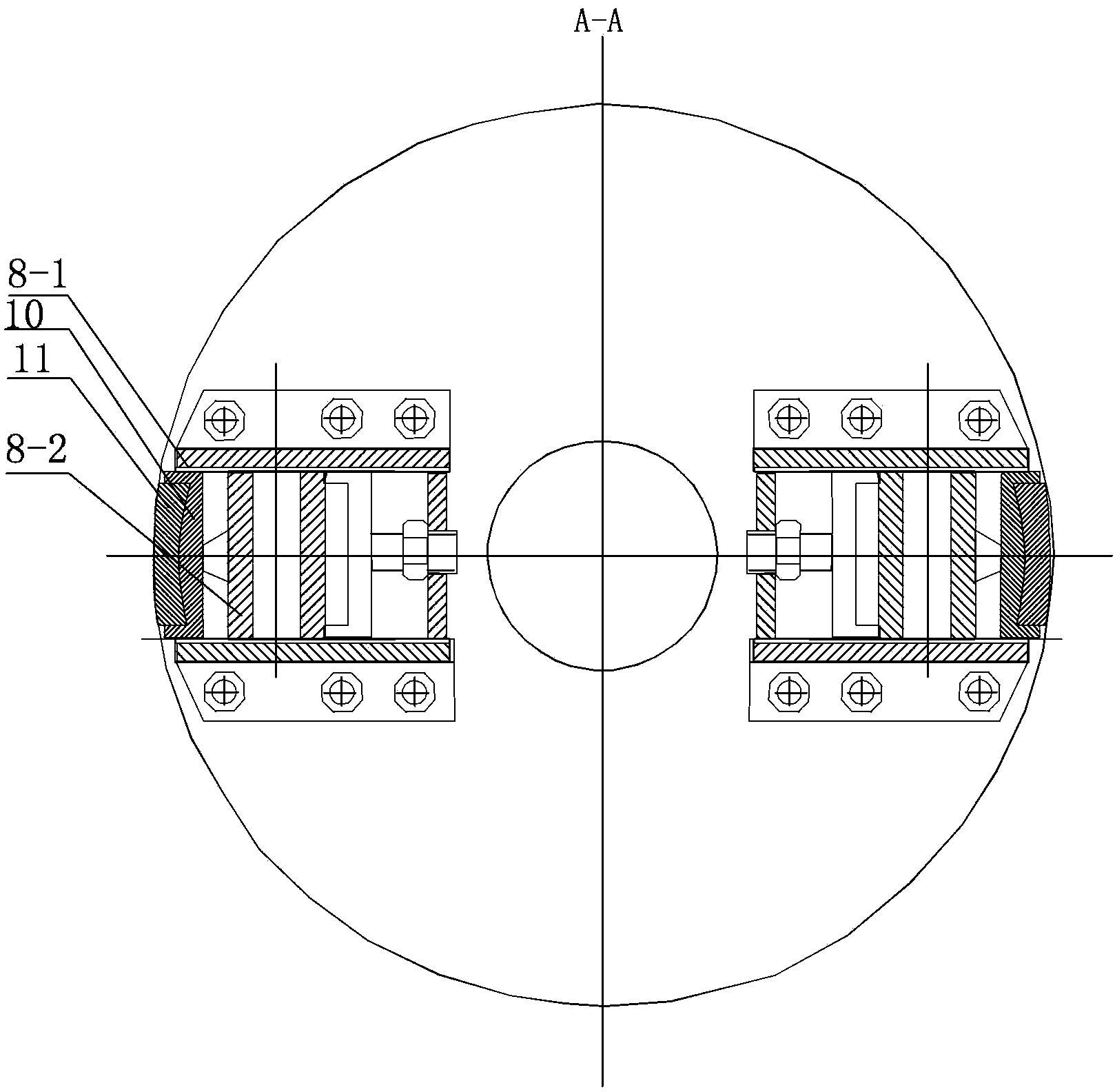
[0010] Specific implementation manner two: combination figure 2 To illustrate this embodiment, the multifunctional bracket 8 of this embodiment is composed of two rails 8-1 and a plurality of cross bars 8-2, the two rails 8-1 are arranged in parallel, and the plurality of cross bars 8-2 are arranged in parallel. Between the rails 8-1 and each crossbar 8-2 is arranged perpendicular to the rail 8-1, the friction plate 11 fixed on the friction plate fixing frame 10 can only run along the brake chassis 12 under the restriction of the multifunctional bracket 8. The relative movement in the radial direction can not be relative rotation. The other embodiments are the same as the first embodiment.

specific Embodiment approach 3

[0011] Specific implementation mode three: combination figure 1 To illustrate this embodiment, the brake disc 4 of this embodiment is provided with a groove 4-1, the upper end of the lever 5 is provided in the groove 4-1, and the groove 4-1 on the brake disc 4 restricts the upper end of the lever 5 to only Relatively move along the radial direction of the brake disc 4 and cannot rotate relatively. The other embodiments are the same as the first embodiment.


PUM


Abstract

The utility model discloses an automatic braking force regulating device for a screw oil pump and particularly relates to an oil field screw oil pump automatic ground braking force regulating device. The problems that during oilfield exploitation, when the screw oil pump halts or is jammed during operation, parts on a ground driving device are thrown out at a high speed, accidents are caused, and the safety of oil field workers is poor are solved. A branch pipe is respectively is rotating connection with a casing and a base, a braking disk connecting pipe is sleeved outside the branch pipe, the braking disk connection pipe is connected with a braking base disk fixedly, the braking base disk is installed on the base, two ratchet wheels are installed on the branch pipe fixedly, pawls are installed on the upper end face of the braking disk, the braking disk is sleeved on the branch pipe, two levers are installed on the braking pipe, balance weight blocks are sleeved on the levers, the levers are connected with multi-functional supports, special-shaped cams are installed on side walls of the levels, two multi-functional supports are installed on the braking base disk fixedly, and a friction sheet is installed on a side wall of a friction sheet fixing support. The device is applied to the technical field of oilfield exploitation.

Description

Technical field [0001] The invention relates to the technical field of oilfield exploitation, in particular to an automatic adjustment device for the ground braking force of a screw oil pump in an oilfield. Background technique [0002] At present, the power source of the screw oil pump in the oil field is the ground motor through the gearbox to change the speed and slowly twist the sucker rod up to several hundred meters to drive the downhole screw pump rotor to rotate and lift the downhole liquid to the ground, due to the screw pump rotor and the surface drive device The distance between the screw pumps is long. Therefore, to make the screw oil pump work, the sucker rod must store enough energy (elastic energy) to drive the downhole screw pump to work; also when the screw pump is stopped or the stuck pump is stopped, due to pumping The driving force of the oil rod disappears instantly, and the ground equipment has anti-reversal, which is easy to cause shutdown. The energy store...

Claims


Application Information

Patent Timeline
Patent Type & Authority Patents(China)
IPC IPC(8): F04C15/00F04C14/28
Inventor 孙光胜
Owner BEIJING SHITONG HUAAO OILFIELD CHEM TECH
Why Eureka
Try Eureka