
Circulating-type water chemical oxygen demand detection photoelectrochemical sensor

A chemical oxygen demand, photoelectrochemical technology, applied in the field of environmental analysis and sensors, nanomaterials, can solve the problems of slow speed, multi-corrosive and toxic substances sensitivity, low sensitivity, etc., achieve constant volume, high sensitivity, avoid photocurrent Effects of Response Error

Inactive Publication Date: 2013-01-09
HEFEI UNIV OF TECH
View PDF9 Cites 18 Cited by
  • Summary
  • Abstract
  • Description
  • Claims
  • Application Information

AI Technical Summary

Problems solved by technology

[0008] The technical problem to be solved by the present invention is to overcome the shortcomings of conventional water chemical oxygen demand (COD) detection methods that are slow and consume more corrosive and toxic substances, and the sensitivity of the existing method for measuring chemical oxygen demand based on photoelectric catalysis is not high. high disadvantage, providing a TiO-based 2 Cyclic photoelectrochemical sensor with nano-array as working electrode for high-sensitivity and rapid detection of organic pollutants in water

Method used


Image

  • Circulating-type water chemical oxygen demand detection photoelectrochemical sensor
  • Circulating-type water chemical oxygen demand detection photoelectrochemical sensor

Examples


Embodiment 1

[0034] TiO 2 The nanotube array was prepared by anodic oxidation method, the electrolyte was ethylene glycol solution containing 0.3mol / L HF, the voltage was 100V, and the time was 6h. Oxidized TiO2 The nanotube array is crystallized by heat treatment at 500° C. for 2 hours.

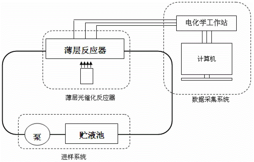
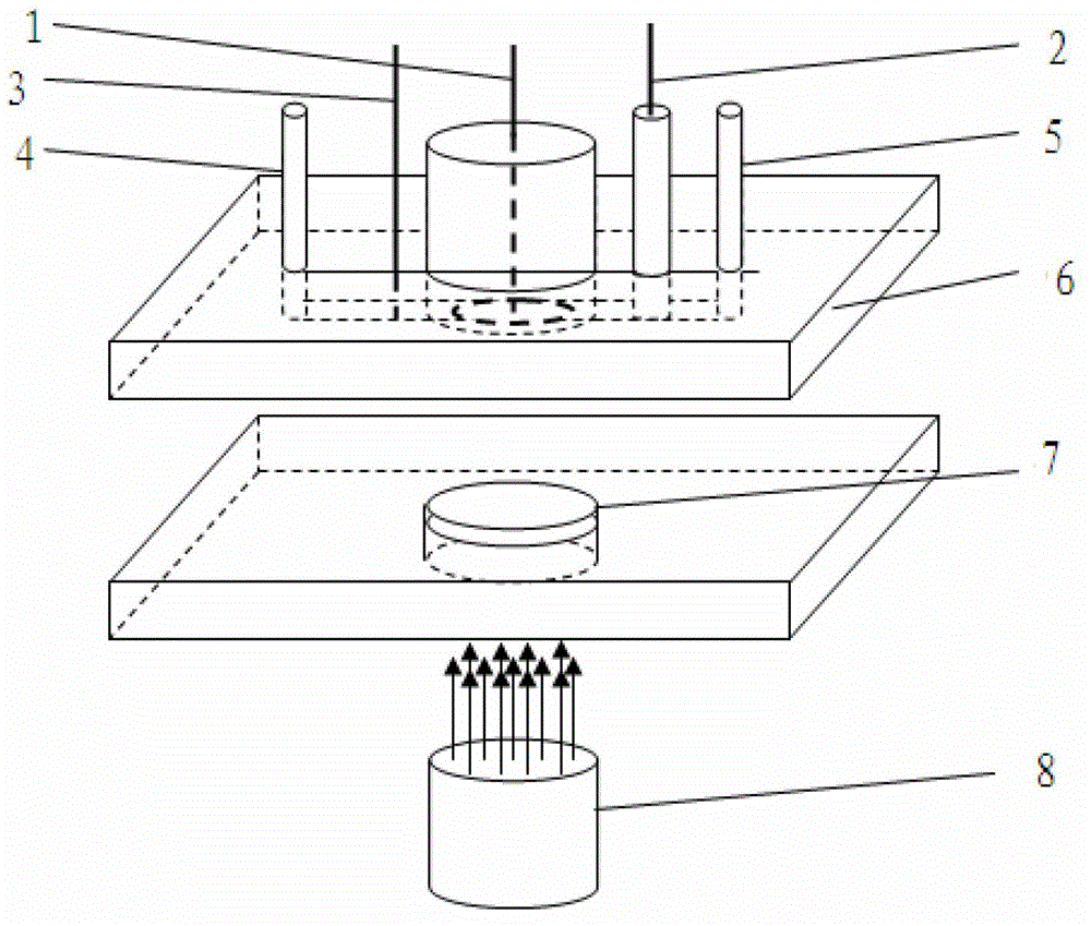
[0035] Connect the various parts of the photoelectrochemical sensor as shown in the attached figure, set the flow rate of the peristaltic pump to 10mL / min, apply a bias voltage of 0.2V in the constant potential mode of the electrochemical workstation, and set the power of the ultraviolet light source to 10% (120mW / cm 2 ), the support solution is 0.05mol / L phosphate buffer (Na 2 HPO 4 and NaH 2 PO 4 mix, pH 7).

[0036] Using photoelectrochemical sensor for glucose detection, the detection sensitivity is 66.6μA / mM (COD0.3469uA / mgL -1 ), the limit of detection is 0.0089mM (COD 1.709mgL -1 ).

Embodiment 2

[0038] The implementation method of this embodiment is the same as that of Embodiment 1, except that the bias voltage applied in the potentiostatic mode of the electrochemical workstation is 0.4V.

[0039] The detection of glucose by photoelectrochemical sensor has a detection sensitivity of 64.2μA / mM (COD0.3344uA / mgL -1 ), the limit of detection is 0.0093mM (COD 1.776mgL -1 ).

Embodiment 3

[0041] The implementation method of this embodiment is the same as that of Embodiment 1, except that the bias voltage applied in the potentiostatic mode of the electrochemical workstation is 0.6V.

[0042] Using photoelectrochemical sensor to detect glucose, the detection sensitivity is 48.4μA / mM (COD0.2521uA / mgL -1 ), the limit of detection is 0.0123mM (COD 2.356mgL -1 ).


PUM

PropertyMeasurementUnit
Wavelengthaaaaaaaaaa

Abstract

The invention relates to the technical field of a nano material, environmenta analysis and a sensor, in particular to a circulating-type water chemical oxygen demand detection photoelectrochemical sensor. The sensor consists of a thin-layer photocatalysis reactor based on an order titanium dioxide (TiO2) nanot tube array, a sample feeding system and a data collection processing system, and the chemical oxygen demand in a water sample is quantitatively detected by dynamically collecting and processing current response in the organic matter photocatalysis degradation process. Since a signal is sourced from the variation of the optical current produced in the process for photocatalyzing and oxidizing the organic matters by utilizing the nano TiO2 nanotube array, no any other strong oxidant is needed. A circulating-type water sample feeding way is adopted, so that the volume of the supporting solution is constant, a stable optical current signal is easy to obtain, the optical current response error caused by the instability for detecting the primary optical current at every time can be avoided, and higher sensitivity can be realized.

Description

technical field [0001] The invention relates to the technical fields of nanomaterials, environmental analysis and sensors, in particular to a circulating photoelectric chemical sensor for detecting chemical oxygen demand in water bodies. Background technique [0002] As more and more organic pollutants are discharged into water bodies, water quality detection and control becomes more and more important. The determination of chemical oxygen demand (COD) is one of the main methods widely used in water quality analysis in various countries, and it is also an important indicator for factory sewage discharge control. The determination methods stipulated in the current national standards are potassium permanganate method and potassium dichromate method. These methods require a long time for sufficient oxidation and consume expensive Ag 2 SO 4 , corrosive H 2 SO 4 , toxic Hg 2+ and Cr 2 o 7 2- and other chemicals. [0003] In order to reduce the oxidation time, the researc...

Claims


Application Information

Patent Timeline
IPC IPC(8): G01N27/26
Inventor 徐光青黄庆明吕珺吴玉程
Owner HEFEI UNIV OF TECH
Learn More