
Zero-flux hall large-current sensor structure

A high current, zero magnetic flux technology, applied in the field of sensors, to achieve the effect of easy adjustment

Inactive Publication Date: 2013-01-09
INST OF PLASMA PHYSICS CHINESE ACAD OF SCI
View PDF8 Cites 2 Cited by
  • Summary
  • Abstract
  • Description
  • Claims
  • Application Information

AI Technical Summary

Problems solved by technology

The new fiber-optic current sensor can measure large currents, but it will cause signal hysteresis when measuring fast current signals, which will affect the stability of the control system; it is expensive, and the price of sensors with a range below 45KA is 450,000 RMB, and the ITER power supply device requires a lot of current Sensors, if all fiber optic current sensors are purchased, the cost is quite high

Method used


Image

  • Zero-flux hall large-current sensor structure
  • Zero-flux hall large-current sensor structure
  • Zero-flux hall large-current sensor structure

Examples


Embodiment Construction

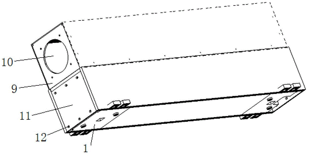
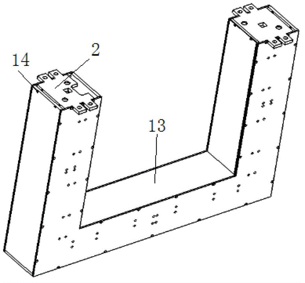
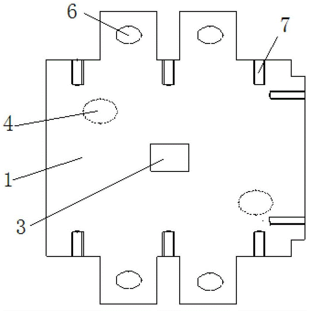
[0020] Such as Figure 1-5 As shown, the structure of a Hall zero-flux high-current sensor includes an upper half structure, a lower half structure, and a connecting part structure. The connecting part structure includes the same upper mounting plate 1, lower mounting plate 2, upper There is a square hole in the middle of the mounting plate 1 and the lower mounting plate 2 as the magnetic core mounting hole 3. The size of the magnetic core mounting hole 3 is slightly larger than the cross section of the magnetic core. There are several circular positioning holes on the lower surface of the upper mounting plate 1. The boss 4, the upper surface of the lower mounting plate 2 are provided with several circular positioning pits 5 that cooperate with the circular positioning boss 4, and the front and rear ends of the upper mounting plate 1 and the lower mounting plate 2 are respectively provided with two Hanging lug 6, the hanging lug 6 on the upper mounting plate 1 is in the same p...


PUM


Abstract

The invention discloses a zero-flux hall large-current sensor structure, which comprises an upper half part structure, a lower half part structure and a connecting part structure, wherein the connecting part structure comprises an upper installation plate and a lower installation plate, which are identical to each other, the upper half part structure comprises two superimposed aluminum plates, two ends of the aluminum plate on the upper part are respectively provided with a circular hole, the periphery of the aluminum plate on the lower part is provided with a plurality of tapping holes C corresponding to tapping holes A on an upper installation plate, the aluminum plate on the lower part and the two upper installation plates are fixed by adopting a screw to penetrate the tapping holes A and the tapping holes C, the lower half part structure comprises a U-shaped aluminum plate, the peripheries of two top ends of the U-shaped aluminum plate are respectively provided with tapping holes D, two top ends of the U-shaped aluminum plates and two lower installation plates are fixed by adopting a screw to penetrate tapping holes B and the tapping holes D, and the upper installation plates and lower installation plates are tightened through a bolt running through a hole on a suspension loop. Through the structural mode, by adjusting an intermediate connecting mechanism, the position of a magnetic core is very easy to adjust.

Description

technical field [0001] The invention relates to a sensor, in particular to a structure of a Hall zero magnetic flux large current sensor. Background technique [0002] The basic principle of Hall zero flux sensor: primary current I 1 The generated magnetic field is passed by the current I of the secondary coil on the secondary side 2 Compensated by the generated magnetic field, so that the Hall device is always in the working state of zero magnetic flux. When the number of primary and secondary turns of the sensor is determined, by measuring the secondary current I 2 can accurately calculate the primary current I 1 . [0003] The Hall zero-flux Hall bidirectional current sensor on the market has a controller based on an analog circuit design. When the sensor measures the current, the transistor is turned on and outputs a certain current value to compensate for the magnetic field generated by the primary loop current. When the transistor is turned on, it works in the li...

Claims


Application Information

Patent Timeline
Patent Type & Authority Applications(China)
IPC IPC(8): G01R19/00
Inventor 王林森王付胜
Owner INST OF PLASMA PHYSICS CHINESE ACAD OF SCI
Learn More