
NSST (NonsubsampledShearlet Transform) domain MRF (Markov Random Field) and adaptive threshold fused remote sensing image change detection method

An adaptive threshold and remote sensing image technology, applied to instruments, character and pattern recognition, computer components, etc., can solve the problems of not considering the relationship between features of different scales, affecting the change detection results, and not being able to obtain the change detection results

Inactive Publication Date: 2013-01-09
XIDIAN UNIV
View PDF4 Cites 13 Cited by
  • Summary
  • Abstract
  • Description
  • Claims
  • Application Information

AI Technical Summary

Problems solved by technology

This method uses the Markov chain to fuse multiple scale information and spatial context information, which improves the accuracy of change detection results, but the final likelihood energy function obtained is only a simple superposition of the likelihood energy functions of each scale. The relationship between features of different scales is not considered, and the assumption of conditional independence cannot be strictly satisfied, which affects the accuracy of change detection results to a certain extent
[0008] The above-mentioned change detection method cannot balance the two characteristics of reducing false detection and maintaining edge information well, so that the detection result or edge information remains good, but there are more false detections and more noise points; or less false detections and less noise points , but the edge information is not well preserved, and ideal change detection results cannot be obtained

Method used


Image

  • NSST (NonsubsampledShearlet Transform) domain MRF (Markov Random Field) and adaptive threshold fused remote sensing image change detection method
  • NSST (NonsubsampledShearlet Transform) domain MRF (Markov Random Field) and adaptive threshold fused remote sensing image change detection method
  • NSST (NonsubsampledShearlet Transform) domain MRF (Markov Random Field) and adaptive threshold fused remote sensing image change detection method

Examples


Embodiment 1

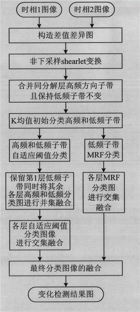
[0063] The present invention is a remote sensing image change detection method of fusion of NSST domain MRF and adaptive threshold value, which mainly processes remote sensing images. The image processing requires a large-capacity computer as hardware support, and uses matlab and other software to realize image processing. see figure 1 , remote sensing image change detection includes the following steps:

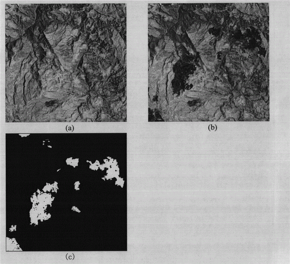
[0064] Step 1, for the two input remote sensing images X of the same area with different phases of size I×J that have been registered 1 and x 2 ,Such as figure 2 (a) and figure 2 As shown in (b), the image X 1 and x 2 The pixel gray value X at the corresponding position (m,n) in the space 1 (m,n) and X 2 (m, n) to calculate the difference and get the difference X d (m,n)=|X 1 (m,n)-X 2 (m, n)|, where, m and n are the row and column numbers of the remote sensing image respectively, m=1, 2,..., I, n=1, 2,..., J, thus obtaining a difference image x d .

[0065] S...

Embodiment 2

[0114] The remote sensing image change detection method of NSST domain MRF and adaptive threshold fusion is the same as embodiment 1, refer to figure 1 , the implementation steps of the present invention are further described as follows:

[0115] Among them, in step 5, a high-frequency adaptive threshold classification map B of the sth layer is obtained h,s The specific operation is:

[0116] (5a) Using the high-frequency initial classification map of the s-th layer obtained in step 3, calculate the high-frequency sub-band D of this layer h,s The prior probability of the variation class in and the prior probabilities of the invariant class

[0117] p ( ω h , c s ) = N h , c s ...

Embodiment 3

[0140] The remote sensing image change detection method of NSST domain MRF and adaptive threshold value fusion is the same as embodiment 1-2, wherein the value of the final iteration number K in the step (6a) is selected as 15, and the MRF classification map of each layer that obtains like this and K= Compared with the same layer, the MRF classification diagrams of each layer obtained at 5 o'clock have fewer missed detections and increased false detections; the value of K is selected as 15, and the final MRF classification diagrams obtained by intersection and fusion of the MRF classification diagrams of all decomposed layers are the same as K= Compared with the final MRF classification map at 5 o'clock, the missed detection is reduced and the false detection is increased; the value of K selected as 15 has little effect on the final change detection result map, but its efficiency is reduced, that is to say, the selection of K Efficiency is slightly affected when the value is in...


PUM


Abstract

The invention discloses an NSST (NonsubsampledShearlet Transform) domain MRF (Markov Random Field) and adaptive threshold fused remote sensing image change detection method, which solves the problem that edge information of a change region cannot be kept while a miscellaneous point is removed in the conventional change detection method. An implementation process for the method comprises the following steps of: inputting two remote sensing images of different time phases and constructing a difference image by using a difference value method; performing nonsubsampledShearlet decomposition on the difference image; combining a directional sub-band of each layer into a high-frequency sub-band; performing adaptive threshold classification on a high-frequency sub-band and a low-frequency sub-band of each layer to obtain a high-frequency adaptive threshold classification chart and a low-frequency adaptive threshold classification chart at each layer; performing MRF classification on the low-frequency sub-band of each layer respectively to obtain an MRF classification chart for each layer; and fusing the classification results to obtain a change detection result. The method has the advantages of high anti-noise property, high edge information retention capacity, less false drop of a detection result and high accuracy. The method is used for the fields such as urban area change monitoring, forestry and vegetation change monitoring and military target monitoring.

Description

technical field [0001] The invention belongs to the field of digital image processing, relates to remote sensing image change detection, and mainly relates to a non-subsampled Shearlet Transform (Nonsubsampled Shearlet Transform, NSST) domain Markov Random Field (Markov Random Field, MRF) and adaptive threshold fusion remote sensing Image change detection, specifically a remote sensing image change detection method based on NSST domain MRF and adaptive threshold fusion. This method is used to classify difference images in change detection of remote sensing images. Background technique [0002] The change detection of remote sensing images is mainly based on the differences in electromagnetic spectrum characteristics or spatial structure characteristics of remote sensing images in different time phases in the same area. By analyzing and extracting these differences, the transformation of ground object types or changes in internal conditions and states can be realized. It has...

Claims


Application Information

Patent Timeline
IPC IPC(8): G06K9/62
Inventor 王桂婷焦李成刘博伟公茂果侯彪王爽钟桦田小林
Owner XIDIAN UNIV
Learn More