Parallel type water rocket launcher

A technology for launching devices and water rockets, which is applied to educational appliances, instruments, teaching models, etc., can solve the problems of model rockets polluting the environment, the parent body of multiple parallel sub-rockets without a matching launch device, etc., so as to achieve convenience and improve efficiency. Effect

Inactive Publication Date: 2013-01-09
施胜南
View PDF3 Cites 1 Cited by
  • Summary
  • Abstract
  • Description
  • Claims
  • Application Information

AI Technical Summary

Problems solved by technology

[0004] The purpose of the present invention is to provide a parallel water rocket launching device to solve the problem that the existing model rockets pollute the environment and the parent body of multiple parallel sub-rockets has no matching launching device

Method used


Image

  • Parallel type water rocket launcher

Examples


specific Embodiment approach 1

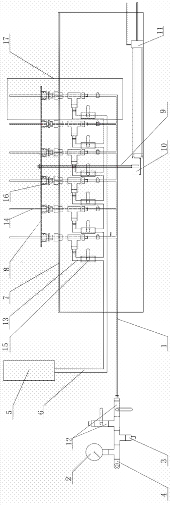
[0008] Specific implementation mode one: combine figure 1 Describe this embodiment, the launch device of this embodiment includes an inflation pipeline 1, an air pressure gauge 2, an air needle 3, an air pressure adjustment valve 4, a water injection device 5, a first connecting pipe 6, a launch platform 7, a launch plate 8, and a lead screw 9. Cylinder 10, intake pipeline 14, two first ball valves 12 and a plurality of second connecting pipes 13, the side wall of the inflation pipeline 1 is respectively connected with the air pressure valve 4, air pressure gauge 2, air needle 3 and two The first ball valve 12 is communicated, and one end of the inflation pipeline 1 is communicated with the intake pipe 14 of a plurality of water rocket launchers 17, and the water injection device 5 is communicated with an end of the first connecting pipe 6 respectively, and the first connecting pipe 6 is respectively connected with multiple One end of each second connecting pipe 13 communicate...

specific Embodiment approach 2

[0010] Specific implementation mode two: combination figure 1 To describe this embodiment, the launching device of this embodiment further includes a solenoid valve 11 , and the movement of the guide rod of the cylinder 10 is realized by turning on and off the solenoid valve 11 . The up-and-down movement of the guide rod of the cylinder 10 is realized by turning on and off the power of the solenoid valve 11. When the power is turned on, the guide rod of the cylinder 10 moves downward, and the launch plate 8 also moves downward, and simultaneously presses the launch sleeve 16 to play a role in each sub-section. The body water rockets are launched at the same time, so that the parent water rocket can be launched smoothly, and finally the parallel launch of the water rockets is realized. Other implementation manners are the same as the specific implementation manner 1.

[0011] Working principle: install each sub-body water rocket of the parent water rocket into the launch sleev...


PUM


Abstract

The invention relates to the field of model rockets, in particular to a parallel type water rocket launcher. The launcher solves the problems of the existing model rockets that the environment is polluted, and a parent of a plurality of parallelly-connected subrockets does not have a matched launching device. A lateral wall of an inflation pipeline is respectively communicated with a pressure adjusting valve, a pressure meter, a gas needle and two first ball valves. One end of the inflation pipeline is communicated with a plurality of gas inlet pipes of the water rocket launcher, a water injection device is respectively communicated with a first connecting pipe, the first connecting pipe is respectively communicated with a plurality of second connecting pipes, each second connecting pipe is communicated with a plurality of gas inlet pipe lateral walls of the launcher, each second connecting pipe is provided with a second ball valve, the water rocket launcher is fixed on a launching platform, a launching plate is arranged on the launching platform parallelly, the launching plate is provided with a plurality of launching sleeves of the water rocket launcher, a lead screw is fixedly connected onto the launching plate, and the lead screw is in transmission connection with a guiding rod of an air cylinder. The parallel type water rocket launcher is applicable to the model rockets.

Description

technical field [0001] The invention relates to the field of model rockets, in particular to a parallel water rocket launching device. Background technique [0002] Because the model rocket competition has strict regulations on solid propellant motors, proven motors must be used. However, there are no strict regulations on using a water rocket as the engine of a model rocket. Because the solid propellant motor uses propellant as power, there is a great potential safety hazard, and a large amount of smoke and dust and exhaust gas generated by combustion produce a large amount of pollution to the environment. [0003] Generally, multiple sub-body solid propellant motors are connected in parallel on the model rocket to increase the thrust. Therefore, if the water rocket wants to increase the thrust, multiple sub-body water rockets must be connected in parallel. Contents of the invention [0004] The purpose of the present invention is to provide a parallel water rocket laun...

Claims


Application Information

Patent Timeline
Patent Type & Authority Applications(China)
IPC IPC(8): G09B25/02
Inventor 施胜南
Owner 施胜南
Why Eureka
Try Eureka