Compensation method for more input computing amplifiers and its output voltage

A technology of operational amplifiers and compensation methods, which is applied in the direction of improving amplifiers to reduce temperature/power supply voltage changes, differential amplifiers, DC-coupled DC amplifiers, etc., which can solve problems such as errors and achieve the effect of improving accuracy

Active Publication Date: 2016-03-23
NOVATEK MICROELECTRONICS CORP
View PDF3 Cites 0 Cited by
  • Summary
  • Abstract
  • Description
  • Claims
  • Application Information

AI Technical Summary

Problems solved by technology

And this gm H and gm L The difference between them also causes errors in the output voltage Vo of the multi-input operational amplifier 100 under the specific combination of input voltages V1~VK, which cannot be ideally shown in Table 1.

Method used


Image

  • Compensation method for more input computing amplifiers and its output voltage
  • Compensation method for more input computing amplifiers and its output voltage
  • Compensation method for more input computing amplifiers and its output voltage

Examples


Embodiment Construction

[0033] In the following, a number of implementation examples are provided for the compensation method of the output error of the multi-input operational amplifier, so that those skilled in the art can understand and implement.

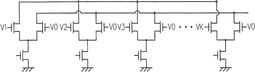
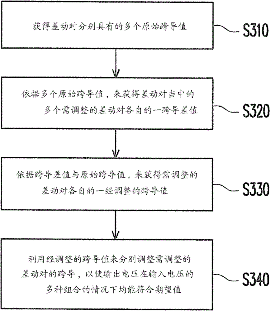
[0034] image 3 It is a flowchart of a compensation method for an output error according to an embodiment. This output error compensation method 300 is suitable for applications such as figure 1 The multi-input operational amplifier shown. Figure 4 Then it is a schematic diagram of a multi-input operational amplifier 400 according to an embodiment. Please refer to the following image 3 and Figure 4 for easy understanding.

[0035] It is worth noting that the following is the compensation method 300 using the output error applied to Figure 4 Four-input operational amplifier 400 to explain the details of the process. However, the output error compensation method 300 can be applied to multi-input operational amplifiers with various numbers of i...


PUM


Abstract

The invention relates to a multi-input operational amplifier and a compensation method for output voltage of the same. The compensation method comprises the steps of: at first, obtaining a plurality of respective original transconductance values of a differential pair under the condition that the input voltage received by the differential pair is a combination of specific levels; obtaining respective transconductance differences of a plurality of differential pairs to be adjusted among the differential pairs according to the original transconductance values; then obtaining the respective adjusted transconductance values of the differential pairs to be adjusted according to the transconductance differences and the original transconductance values; and finally, respectively adjusting the transconductance of the differential pairs to be adjusted according to the adjusted transconductance values, so that the output voltage can reach the expected value in the cases of multiple combinations of the input voltage.

Description

technical field [0001] The invention relates to a multi-input operational amplifier, and in particular to a compensation method for the output error of the multi-input operational amplifier. Background technique [0002] In consideration of reducing the layout area of ​​an integrated circuit (Integrated Circuit, IC), output buffers of many display driving ICs are constructed by using multi-input operational amplifiers. This multi-input operational amplifier can generate a combined output voltage by interpolating several different voltage values. [0003] Please refer to figure 1 The internal circuit diagram of the input stage of a known multi-input operational amplifier is shown. Such as figure 1 As shown, the input stage of the multi-input operational amplifier has K differential pairs, where K is a positive integer greater than 1, such as 4. Each differential input pair has an input end coupled to an output end of the multi-input operational amplifier for receiving the...

Claims


Application Information

Patent Timeline
Patent Type & Authority Patents(China)
IPC IPC(8): H03F3/45H03F1/30
Inventor 黄如琳卓均勇刘育韶
Owner NOVATEK MICROELECTRONICS CORP
Why Eureka
Try Eureka