Integrated heterodyne array receiver of millimeter and sub-millimeter wave bands
A millimeter-wave and sub-millimeter technology, applied in the direction of electrical components, transmission systems, etc., can solve the problems of unsupported waveguide-type local oscillator distribution, bulky receiver system, lack of pairing of one-dimensional sub-arrays, etc., to reduce electrical welding Risk of point breaks, reduced difficulty, effects of improved uniformity and reliability
- Summary
- Abstract
- Description
- Claims
- Application Information
AI Technical Summary
Problems solved by technology
Method used
Image
Examples
Embodiment 1
[0040] Embodiment 1 Millimeter wave, submillimeter wave band heterodyne array receiving module
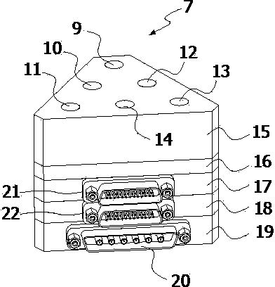
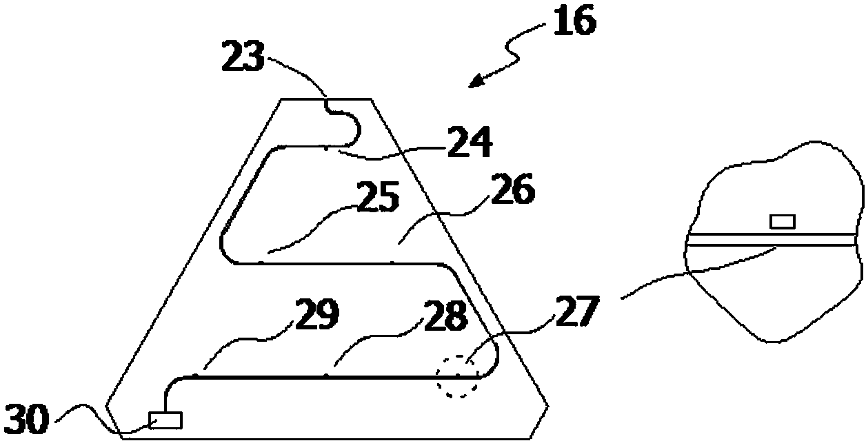
[0041] The millimeter-wave and submillimeter-wave band heterodyne array receiving module adopts an isosceles trapezoidal columnar module with a cross-section and a base angle of 60 degrees, and is made of pure copper with gold plating. as attached figure 1 As shown, the subarray modules are layered by function. According to the order of signal transmission, the top layer is the horn antenna layer (15), which integrates 6 corrugated horn antennas (9-13). The second layer is the local oscillator distribution layer (16), which realizes the distribution of local oscillators in the 6 pixels; the third layer is the mixer circuit layer (17), which completes the frequency mixing of the input signal and the reference signal. The voltage bias required by the mixer is input through a 25-core micro-D connector (21); the fourth layer is a low-noise amplifier layer (18), which performs low-no...
Embodiment 2
[0043] Embodiment 2 Heterodyne Array Receiver in Millimeter Wave and Submillimeter Wave Bands
[0044] The millimeter-wave and submillimeter-wave band heterodyne array receivers specifically connect the input waveguide port of the heterodyne array receiving module in Embodiment 1 to a local oscillator transceiver module through pin positioning and screws, and the local oscillator transceiver module uses a corrugated horn. The antenna receives the local oscillator signal.
Embodiment 3
[0045] Embodiment 3 Millimeter wave, submillimeter wave band integrated heterodyne array receiver
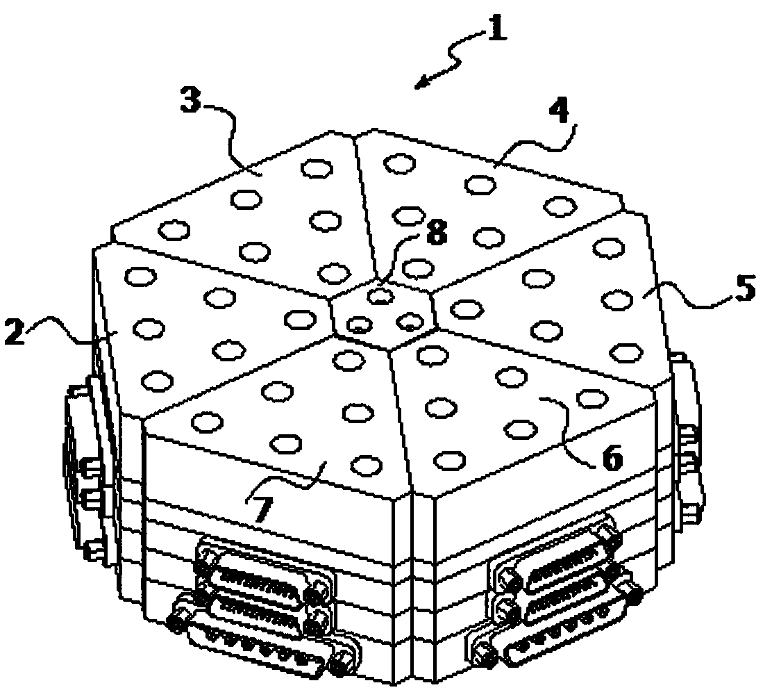
[0046] as attached image 3 As shown, 6 heterodyne array receiving modules described in Embodiment 1 are selected to form a regular hexagonal outline 36-pixel integrated heterodyne array receiver (1), and the center of the regular hexagonal array is a 6-prism shaped local oscillator transceiver module (8). in the attached Figure 4 The two sub-array modules are hidden in the middle, showing the location of the local oscillator transceiver module. The local oscillator signal input ports of the six sub-array modules surround the local oscillator transceiver module (8). as attached Figure 5 As shown, the local oscillator transceiver module consists of a corrugated horn antenna (31) and 6-way power dividers (32-33). The waveguide power divider is processed on the upper surface of (33), and the waveguide circuit structure is split on the H end face of the waveguide, and the two...
PUM
 Abstract
Description
Claims
Application Information
 - R&D
- Intellectual Property
- Life Sciences
- Materials
- Tech Scout
- Unparalleled Data Quality
- Higher Quality Content
- 60% Fewer Hallucinations
Browse by: Latest US Patents, China's latest patents, Technical Efficacy Thesaurus, Application Domain, Technology Topic, Popular Technical Reports.
© 2025 PatSnap. All rights reserved.Legal|Privacy policy|Modern Slavery Act Transparency Statement|Sitemap|About US| Contact US: help@patsnap.com


