Bank note placing and taking method for lower box of automatic teller machine (ATM) and lower box structure

A technology of ATM machine and driving mechanism, which is applied in the direction of transportation and packaging, item supply, and delivery of items, etc., which can solve the problems of insufficient banknote storage capacity of ATM machines, reduce the use efficiency of ATM machines, and prevent ATM machines from being used externally. The effect of using efficiency, reducing the frequency of cleaning and adding banknotes, and increasing the capacity of banknotes

Active Publication Date: 2013-01-16
SHENZHEN YIHUA COMP +2
View PDF9 Cites 8 Cited by
  • Summary
  • Abstract
  • Description
  • Claims
  • Application Information

AI Technical Summary

Problems solved by technology

Considering the convenience of operation by the users and equipment managers of the all-in-one cash deposit and withdrawal machine, the height H of the lower box rack has certain restrictions and cannot be increased arbitrarily.
Therefore, horizontally placing the cash box in the lower case limits the number of cash boxes of the ATM machine, and it is difficult for the ATM machine to expand the capacity of the banknote
[0009] The banknote capacity of the ATM machine is not enough, and the equipment management personnel need to increase the number of times of cleaning and adding banknotes. When cleaning the machine and adding banknotes, the ATM machine cannot be used externally, which reduces the efficiency of the ATM machine.

Method used


Image

  • Bank note placing and taking method for lower box of automatic teller machine (ATM) and lower box structure
  • Bank note placing and taking method for lower box of automatic teller machine (ATM) and lower box structure
  • Bank note placing and taking method for lower box of automatic teller machine (ATM) and lower box structure

Examples


Embodiment Construction

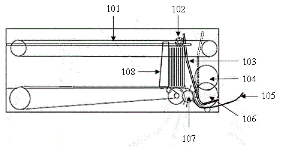
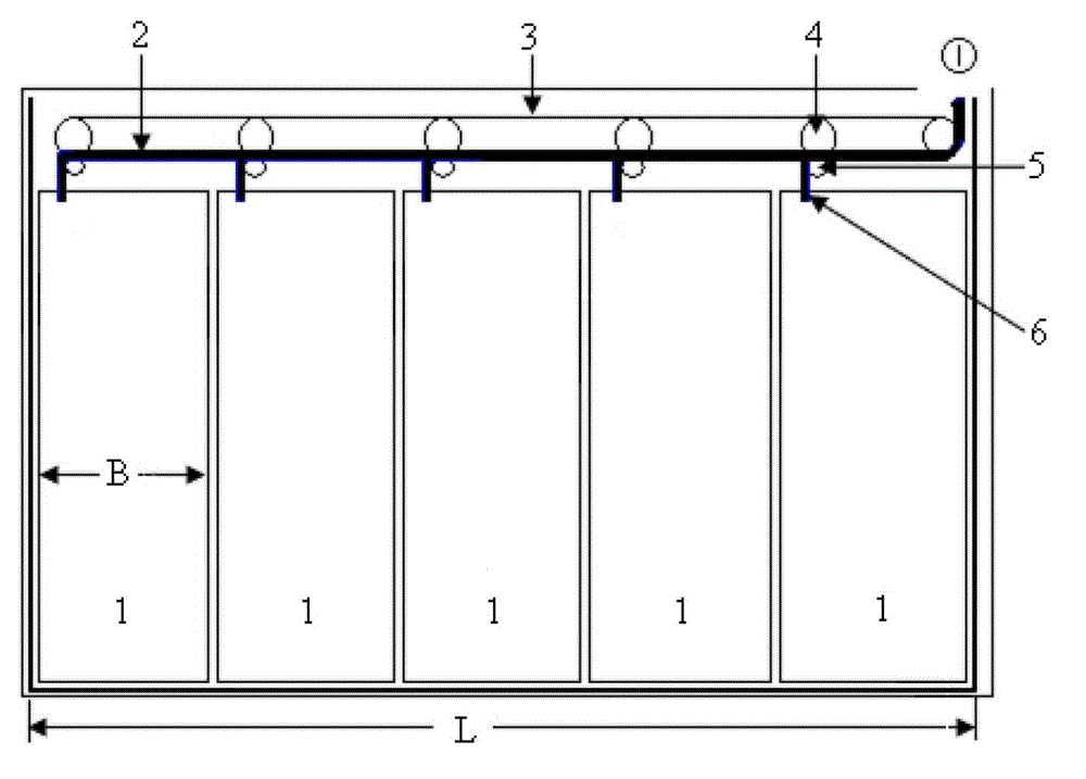
[0040] exist image 3 In the shown embodiment of the lower case structure of the ATM of the present invention, it includes a frame, a conveyor belt 7 , a transport channel 6 for banknotes, 5 cash boxes and 5 guide vanes 9 .

[0041] Each cash box 1 includes a banknote inlet and outlet 10 , and each banknote inlet and outlet 10 corresponds to a guide vane 9 .

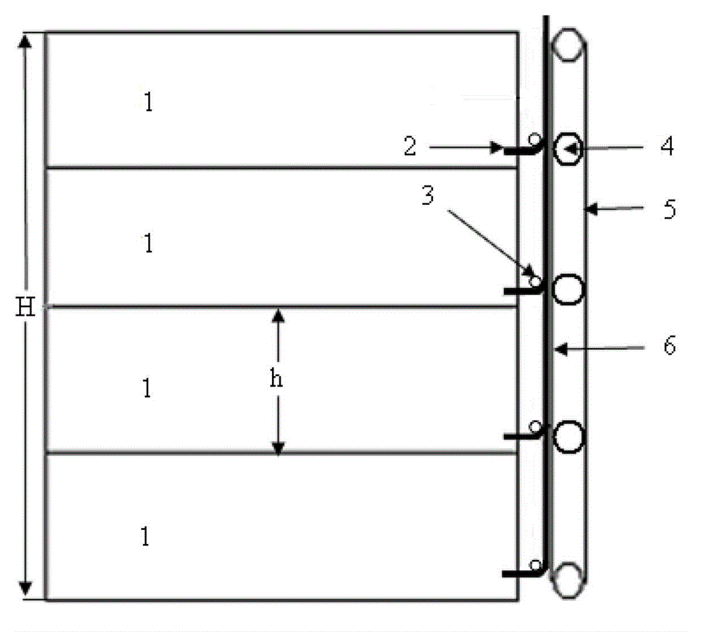
[0042] Five cash boxes 1 are placed vertically and arranged side by side in the slots of the frame. The inlet and outlet banknote opening 10 of the banknote box 1 is located at the top of the banknote box 1 with the opening facing upward.

[0043] The guide vanes 9 are arranged above the inlet and outlet openings 10 of the cash box 1 . The transmission belt 7 is arranged above the guide vane 9 along the direction in which the cash boxes 1 are arranged, driven by the transmission wheel 8, the transmission belt 7 and the banknote friction drive the banknote transmission, and the transmission channel 6 of the banknote ( ...


PUM


Abstract

The invention discloses a bank note placing and taking method for a lower box of an automatic teller machine (ATM) and a lower box structure. Bank notes are arranged on a conveying channel above a plurality of bank note boxes transversely, a bank note inlet / outlet is arranged on top of each bank note box, the bank note boxes are arranged vertically, and the bank notes arranged in the bank note boxes vertically are placed in stacking mode vertically. The lower box structure comprises a machine frame, a conveying belt, a conveying channel of the bank notes, a plurality of bank note boxes and a plurality of guiding blades. The plurality of bank note boxes are arranged vertically and arranged on a machine support transversely and parallelly, the bank note inlets / outlets of the bank note boxes are arranged on top of the bank note boxes, openings face upwards, and the guiding blades are arranged above the bank note inlets / outlets. The conveying belt is arranged above the guiding blades along the arranging direction of the bank note boxes, the conveying channel of the bank notes is arranged between the conveying belt and the guiding blades. The bank note placing and taking method for the lower box of the ATM and the lower box structure simplify bank note box structure, fully use internal space of a deposition and withdrawing integrated machine, bank note containing quantity of the device is increased, machine emptying and bank note adding frequency is reduced, and use efficiency of the ATM is improved.

Description

[technical field] [0001] The invention relates to an all-in-one cash deposit and withdrawal machine, in particular to a method for feeding and withdrawing cash from a lower box of an ATM machine and a lower box structure. [Background technique] [0002] The cash box for depositing banknotes in the lower box of the traditional ATM is placed horizontally. Such as figure 1 As shown, the lower box of the ATM machine includes four cash boxes 1 , side pull plates 5 guide vanes 7 , transmission wheels 8 , transmission belts 9 and transmission channels 10 . Each cash box 1 has an inlet and outlet banknote opening 101 through which banknotes enter and exit the cash box. [0003] Each banknote inlet and outlet of the banknote box corresponds to a guide vane 7, and the guide vane 7 controls the banknotes to continue to be conveyed downward or enter the banknote box. [0004] Transmission wheel 8 is driven by motor, and transmission wheel 8 drives transmission belt 9 to rotate. [0...

Claims


Application Information

Patent Timeline
Patent Type & Authority Applications(China)
IPC IPC(8): B65H29/20B65H31/34B65H31/04B65H5/06
Inventor 彭彤鲁涛田志辉
Owner SHENZHEN YIHUA COMP
Why Eureka
Try Eureka