Supercharge Your Innovation With Domain-Expert AI Agents!

Rigid frame continuous beam double-layer urban elevated road

An elevated road and rigid frame technology, which is applied to the field of rigid frame continuous beam double-deck urban elevated roads, can solve the problems that the lateral dimension of the bridge pier cannot be too small, the logistics and traffic flow cannot be cleared, and the national economic development is restricted. High force and small landing area

Active Publication Date: 2015-07-29
江阴金属材料创新研究院有限公司
View PDF8 Cites 0 Cited by
  • Summary
  • Abstract
  • Description
  • Claims
  • Application Information

AI Technical Summary

Problems solved by technology

The current solution: First, the subway is built underground in the city, but the subway can only clear the crowd on the fixed line, but not the logistics and traffic flow, so some cities have built many subways in the vertical and horizontal directions, but the result is still traffic jams
The second is to build an elevated road on the original ground road in order to increase the passing capacity of the road. However, the design scheme of the existing elevated road is: a single-span simply supported beam with a flat head butt joint to the central pier supporting structure. The size should not be too wide, otherwise it will not be stable. The pier of this structure occupies at least two lanes on the ground, and the width of the bridge deck can only be three times the width of the pier. For a two-way 8-lane road, the central pier occupies two lanes. The elevated bridge body also has 6 lanes, and a total of 12 lanes on the bridge and under the bridge, and only 50% more lanes
The effect can be seen immediately, but everyone knows that this move will directly limit the domestic demand for automobiles and restrict the country's economic development, bringing a lot of inconvenience and difficulties to the people

Method used


Image

  • Rigid frame continuous beam double-layer urban elevated road
  • Rigid frame continuous beam double-layer urban elevated road
  • Rigid frame continuous beam double-layer urban elevated road

Examples


Embodiment Construction

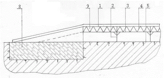
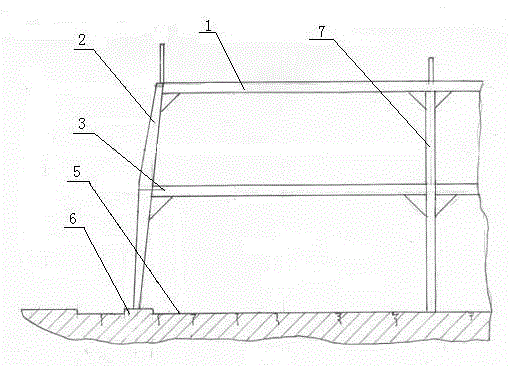
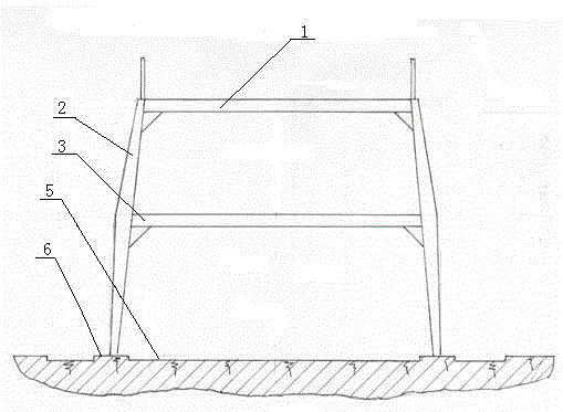
[0018] The present invention will be further described below in conjunction with the accompanying drawings and specific embodiments. Accompanying drawing is the specific embodiment of the present invention. This embodiment is a double-layer urban viaduct with rigid frame continuous girders, including a bridge body, continuous girders 9, roadside columns 2 and bridgehead piers 8, and is characterized in that: the bridge body adopts a frame-shaped continuous girder structure, the upper road 1 and the middle layer The road 3 is the upper and lower sides of the frame, and the two sides between the upper road 1 and the middle road 3 form a truss structure with several oblique rods 4, and the roadside columns 2 and continuous beams 9 form a rigid frame structure, and its upper part is large in size and high in bearing capacity. , the lower part size is small and falls on the roadside flower bed 6, does not account for the area of ​​ground road 5. The bridgehead pier 8 is a rectangu...


PUM


Abstract

The invention discloses a rigid-framed urban double-deck elevated road with continuous beams. A bridge of the rigid-framed urban double-deck elevated road with continuous beams is in a framed continuous beam structure. An upper road tier and a lower road tier are framed. Two sides of structure between the upper road tier and the lower road tier are in truss structures composed of a plurality of diagonals. Roadside pillars and the continuous beams form a rigid frame structure. The upper portion of the rigid frame structure is large in size and high in bearing capacity, and the lower portion of the rigid frame structure is small in size and is rested on roadside flower beds, and no pavement area is occupied. The rigid frame pillars are connected with the bridge rigidly, and the ground part of the elevated road is small in size and can be rested on the roadside flower beds without occupying the original pavement lanes. Owing to the continuous beams, the bridge with multi-support statically indeterminate beams is high in bearing capacity and safety. The double-deck bridge forms the frame, section modulus of the bridge is large, and rigid frame nodes are high in bearing capacity. The double-deck bridge is provided with double decks, one additional pavement is provided, and accordingly trafficability is tripled by that of the original pavement. Space of the existing roads can be utilized fully, and the problem of increasing traffic jam is solved. The rigid-framed urban double-deck elevated road with continuous beams is simple in structure and easy to implement.

Description

technical field [0001] The invention relates to a double-layer urban elevated road with rigid frame continuous beams, which belongs to the technical field of urban construction engineering. Background technique [0002] With the development of the economy, urban traffic is congested, and traffic jams are becoming more and more serious. Current solutions: One is to build underground subways in cities, but subways can only dredge crowds on fixed lines, but cannot dredge logistics and traffic flow, so some cities have built many subways vertically and horizontally, but the result is still traffic jams. The second is to build an elevated road on the original ground road in order to increase the passing capacity of the road. However, the design scheme of the existing elevated road is: a single-span simply supported beam with a flat head butt joint to the central pier supporting structure. The size should not be too wide, otherwise it will not be stable. The pier of this structur...

Claims


Application Information

Patent Timeline
Patent Type & Authority Patents(China)
IPC IPC(8): E01D1/00
Inventor 岑益南
Owner 江阴金属材料创新研究院有限公司
Features
  • R&D
  • Intellectual Property
  • Life Sciences
  • Materials
  • Tech Scout
  • Unparalleled Data Quality
  • Higher Quality Content
  • 60% Fewer Hallucinations
Learn More