Equipment foundation standard mould of multifunctional transformer substation

A technology based on equipment foundation and standard mold, applied in basic structure engineering, construction and other directions, can solve the problems of large construction scope and operation area, affecting the civilized construction environment on site, easy unbalanced grouting and pouring ratio, etc. The working area is small, which is conducive to wide use and promotion, and is not easy to be out of shape and deformed.

Active Publication Date: 2015-04-29
STATE GRID CORP OF CHINA +1
View PDF5 Cites 0 Cited by
  • Summary
  • Abstract
  • Description
  • Claims
  • Application Information

AI Technical Summary

Problems solved by technology

Although the one-time cost is low, easy to assemble, and convenient to use, etc., its disadvantages are that it uses a lot of human resources during installation, the construction scope and work area are large, the workload is large, the construction period is long, the formwork is difficult to fix, and a large amount of square wood is required. And it cannot be reused, causing waste of wood resources, destroying the ecological environment, generating construction waste, which is not environmentally friendly, and affecting the safe and civilized construction environment on site, etc.
In addition, the grouting ratio is easy to be unbalanced, the thickness of the glue layer is uneven, it is not resistant to moisture and soaking, it is easily damaged, and it is prone to explosion. There are quality risks in harsh environments and climatic conditions.

Method used


Image

  • Equipment foundation standard mould of multifunctional transformer substation
  • Equipment foundation standard mould of multifunctional transformer substation

Examples


Embodiment Construction

[0018] The present invention will be further explained below in conjunction with the drawings.

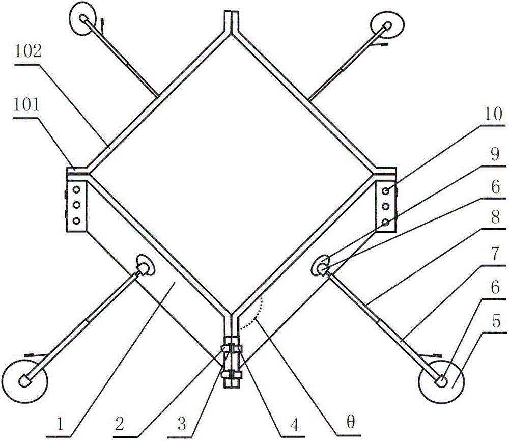
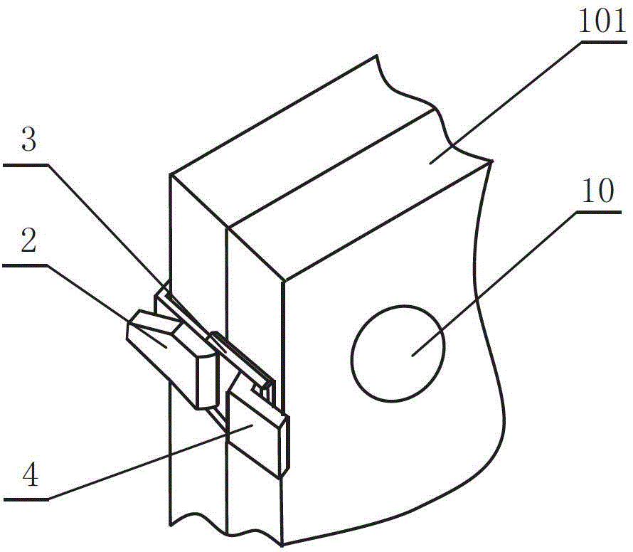
[0019] Such as figure 1 As shown, the present invention is composed of four figure-eight templates 1, each template 1 includes two sides 101 and a straight side 102, the angle θ between the two sides 101 and the straight side 102 is 135 0 One side 101 is provided with a fixed mother board buckle 2, a fixed mother board buckle 2 is provided with a movable buckle ring 3, and the other side 101 is correspondingly provided with a movable daughter board buckle 4. The fixed mother board buckle 2, the movable buckle ring 3, and the movable daughter board buckle 4 are two groups.

[0020] Combine figure 2 As shown, the sides 101 of two adjacent eight-shaped templates 1 are aligned in pairs, and the fixed mother board buckle 2 and the movable sub-board buckle 4 are buckled together by the movable buckle ring 3.

[0021] A hydraulic device is provided on the outside of the template 1, and the hyd...


PUM


Abstract

The invention discloses an equipment foundation standard mould of a multifunctional transformer substation and solves the problems that the existing template cannot be repeatedly used and a resource is wasted. The equipment foundation standard mould is characterized by being formed by four splayed templates; each template comprises two side edges and one straight edge; the included angle between each side edge and the straight edge is 135 degrees; the side edge at one side is provided with a fixed mother board buckle; the fixed parent palate buckle is provided with a movable hasp ring and the side edge of the other side is correspondingly provided with a movable sub-plate buckle; and in order to enable the mould to be used more stably, the outer side of each template is respectively connected with a hydraulic device formed by a hydraulic cylinder, a universal head, a top plate and a bottom plate. According to the equipment foundation standard mould, the length and the width can be adjusted, different specifications of the moulds can be spliced, and the mould can be moved up and down, and moved from the left to the right; the equipment foundation standard mould is convenient to transport, mount, detach and splice and can be repeatedly used in a plurality of transformer substations for many times, so that the machining and mounting costs are reduced; and the reliable safety facility guarantees are provided for the foundation construction work.

Description

Technical field [0001] The invention relates to civil engineering, and more specifically to a standard mold for equipment foundation. Background technique [0002] At present, the basic concrete pouring of equipment such as main transformers, capacitors, reactors, circuit breakers, isolating switches, and main busbar frames in substations mostly uses construction plywood and construction wooden formwork, and there is no standardized formwork. Although the one-time cost is low, easy to assemble, convenient to use, etc., its disadvantages are the large use of human resources during installation, the large construction scope and work area, large workload, long construction period, difficult to fix the template, and a large amount of square wood. And it cannot be reused, causing waste of wood resources, destroying the ecological environment, generating construction waste that is not environmentally friendly, and affecting the safe and civilized construction environment on site. In a...

Claims


Application Information

Patent Timeline
Patent Type & Authority Patents(China)
IPC IPC(8): E02D27/44
Inventor 李淮海朱黎杨玉虎崔锦瑞
Owner STATE GRID CORP OF CHINA
Why Eureka
Try Eureka