Rotating compressor of low pressure structure in shell

A rotary compressor, low-pressure technology, applied in the direction of rotary piston/oscillating piston pump components, liquid fuel engines, components of pumping devices for elastic fluids, etc., can solve high pressure resistance requirements, leakage , sealing and other issues, to avoid installation and sealing problems, low application difficulty, and good workmanship

Active Publication Date: 2013-01-16
GUANGDONG MEIZHI COMPRESSOR
View PDF9 Cites 10 Cited by
  • Summary
  • Abstract
  • Description
  • Claims
  • Application Information

AI Technical Summary

Problems solved by technology

Although this scheme has been improved, there are still some defects: 1. Adding an external oil separator and oil return pipe leads to complex structure and process, and brings additional problems of increased refrigerant quality or high pressure resistance requirements; 2. , When the oil separator is built in, the oil supply path in the center of the crankshaft is connected to the oil pool on the high pressure side, causing sealing and leakage problems, resulting in back pressure guarantee and oil supply difficulties in the low back pressure structure, and complicated oil separation and oil return structures

Method used


Image

  • Rotating compressor of low pressure structure in shell
  • Rotating compressor of low pressure structure in shell
  • Rotating compressor of low pressure structure in shell

Examples


Embodiment 1

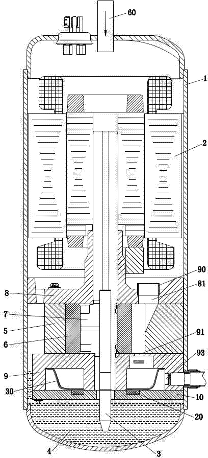
[0027] like figure 1 and figure 2 As shown, a rotary compressor with a low-pressure structure in the shell includes a closed shell 1, an air suction pipe 60 arranged on the top of the shell 1, a motor 2 set in the shell 1, a compression part, and an oil pump 3 ; The inner bottom of the housing 1 is provided with a first oil pool 4, and the compression part includes a cylinder 5 with a compression chamber, a piston 6 and a sliding plate 70 accommodated in the cylinder 5, and an eccentric crankshaft 7 that drives the piston 6 to rotate eccentrically. The upper end surface and the lower end surface of the cylinder 5 also support the upper bearing 8 and the lower bearing 9 of the eccentric crankshaft 7, wherein the upper bearing 8 is provided with an air inlet 81 communicating with the compression chamber, and an internal suction air inlet 81 is installed in the air inlet 81. Pipe 90, the height of the inner suction pipe 90 protruding from the end surface of the air inlet 81 is ...

Embodiment 2

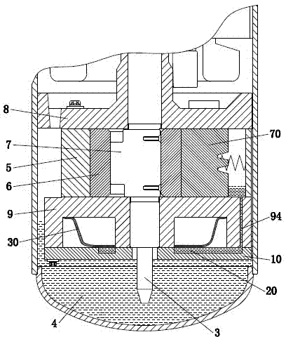
[0040] The basic structure of this embodiment is the same as that of Embodiment 1, the difference is that Figure 5 As shown, the muffler 30 is provided with a dividing plate 40, and a gap is provided between the edge of the dividing plate 40 and the muffler 30. The dividing plate 40 divides the muffler 30 into an upper space whose volume is M and whose volume is N. The lower space, the volume relation between the upper space and the lower space is: M=4N.

[0041] In this way, the gas discharged from the gas outlet 91 has a certain oil separation effect when flowing in the upper space, and the separated oil flows to the lower space through the gap, avoiding the secondary contact between the separated oil and the gas, and further improving the oil separation. Effect.

Embodiment 3

[0043] The structure of this embodiment is basically the same as that of Embodiment 2, the difference is that Image 6 As shown, a baffle 50 is provided between the second oil pool 20 and the exhaust hole 93 .

[0044] The baffle plate 50 can be installed independently, and can also be designed as an integral body with the muffler 30 . The baffle plate 50 prevents the gas from contacting the oil again before entering the exhaust hole 93, thereby improving the oil separation effect. In this way, the gas discharged from the compressor contains less oil, which improves the energy efficiency level of the refrigeration system.


PUM


Abstract

The invention belongs to the technical field of piston type rotating compressors, and discloses a rotating compressor of a low pressure structure in a shell. The invention is characterized in that a cover board (10) is arranged below a lower bearing (9), a closed cavity is arranged between the lower bearing (9) and the cover board (10), a second oil pond (20) is arranged in the cavity, and an air outlet (91) is communicated with an exhaust hole (93) through the cavity; and the lower bearing (9) is provided with an oil supply hole (94) of a backpressure cavity communicated with the second oil pond (20) and a cylinder (5). According to the invention, through the cover board and an oil supply path of the backpressure cavity in the lower bearing, the oil supply of the backpressure cavity is effectively ensured, and the rotating compressor has the advantages of simple structure, good manufacturability, low actual application difficulty, safety and reliability.

Description

technical field [0001] The invention belongs to the technical field of piston rotary compressors, and in particular relates to a rotary compressor with a low-pressure structure in a housing with a built-in oil separation structure. Background technique [0002] The compressor is considered the heart of the refrigeration system. Existing compressors are mainly divided into piston compressors, screw compressors, centrifugal compressors, etc., wherein the piston compressors include high-pressure rotary compressors and low-pressure rotary compressors. [0003] Although high-pressure rotary compressors are widely used, there are still many problems, such as: liquid refrigerant may enter the compression cavity, resulting in wet compression; impurities will enter the compression cavity, damage the compression parts, affect the service life and compression efficiency; In a high-temperature environment, the operating efficiency is low and the reliability is poor; the oil collecting ...

Claims


Application Information

Patent Timeline
Patent Type & Authority Applications(China)
IPC IPC(8): F04C29/02F04C29/06
Inventor 高斌
Owner GUANGDONG MEIZHI COMPRESSOR
Why Eureka
Try Eureka