
Pressure guiding tube blockage detecting system and detecting method

A diagnostic method and diagnostic system technology, applied in pipeline systems, measuring fluid pressure, testing of machine/structural components, etc., can solve problems such as difficulty in utilization, reduction of amplitude, and difficulty, so as to improve sensitivity and easily change pressure sloshing , easily detectable effects

Inactive Publication Date: 2014-12-24
YAMATAKE HONEYWELL CO LTD
View PDF15 Cites 0 Cited by
  • Summary
  • Abstract
  • Description
  • Claims
  • Application Information

AI Technical Summary

Problems solved by technology

However, in general, the higher the frequency of pressure sloshing, the smaller the amplitude, so it is difficult to use
Therefore, it is not easy to use only higher frequency components to solve the problem

Method used


Image

  • Pressure guiding tube blockage detecting system and detecting method
  • Pressure guiding tube blockage detecting system and detecting method
  • Pressure guiding tube blockage detecting system and detecting method

Examples


reference example 1

[0102] In Embodiment 1, the container 10 is set as the deformation rate increasing unit, but as Figure 10 As shown, by increasing the inner diameter of part or all of the pressure guiding tube 3, the volume of the fluid 7 located between the blockage (occlusion) 6 and the pressure signal generator 1 can also be increased to obtain the same pressure as in the first embodiment. Effect.

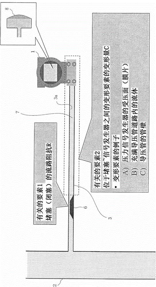
[0103] Figure 10 Among them, the corner of the L-shaped curved pressure guiding tube 3 is used as a site that is easy to be blocked, and the inner diameter of the pressure guiding tube 3 on the inner side than the corner is increased. For example, when the inner diameter is tripled, the volume occupied by the fluid and its deformation amount are nine times larger. This reference example 1 is also the same as the first embodiment, and is mainly effective for compressive fluids. In addition, the magnitude of the effect depends on the position of the blockage (occlusion) 6 .

[0104] [Embodim...

reference example 2

[0115] In Embodiment 2, a member 13 having a diaphragm 12 is provided as a deformation rate increasing unit, but in Figure 13 In the shown structure, the same effect as that of the second embodiment can be obtained by using a material or a structure that is easily deformed by a pressure change for the pressure guide tube 3 .

[0116] When the pressure of the fluid in the pressure guiding tube 3 changes, the pressure guiding tube 3 expands and contracts in the diameter direction. That is, the diameter becomes larger as the pressure increases, and the diameter decreases as the pressure decreases. The pressure guiding pipe 3 is generally a pipe made of metal. Also, the amount of expansion and contraction with respect to pressure changes is often small. Here, if the material of the pressure guiding tube 3 is made of more easily deformable resin or soft metal, or the thickness of the wall 3a of the pressure guiding tube 3 is reduced, the deformation rate of the pressure guiding ...


PUM


Abstract

A vessel is attached to a pressure guiding tube near the point of connection between a process pipe and a pressure transmitter. Doing so increases the rate of deformation, relative to a change in pressure, of a fluid when the fluid is a compressible fluid, making the change in the pressure fluctuation more easily detected, thereby increasing the sensitivity of detection of blockages in the pressure guiding tube. If the fluid is a non-compressible fluid, then a part that has a diaphragm (a pressure bearing surface that deforms easily through pressure) is connected instead of the vessel.

Description

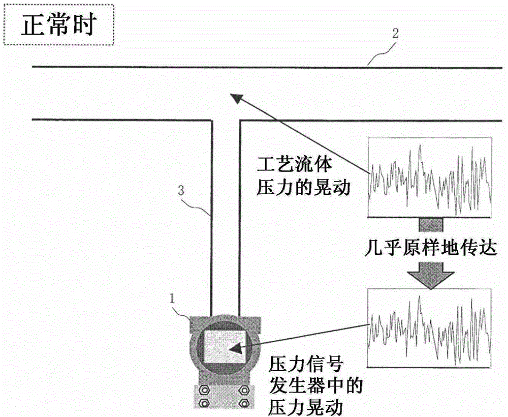
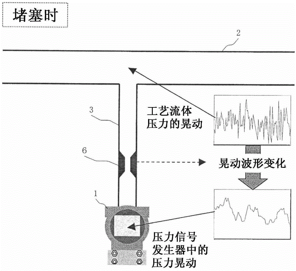
technical field [0001] The invention relates to a clogging diagnosis system and a diagnostic method for diagnosing clogged pressure guiding pipes generated in pressure guiding pipes branched from process pipelines. Background technique [0002] Pressure signal generators or differential pressure signal generators have long been used in the process industry, for example, to detect process variables and control process processes. A pressure signal generator is also called a pressure transmitter, and a differential pressure signal generator is also called a differential pressure transmitter. The pressure signal generator is a component for measuring absolute pressure or gauge pressure, and the differential pressure signal generator is a component for measuring the differential pressure between two points, which is used for the measurement of process variables such as pressure, flow, liquid level, and specific gravity. In general, when measuring a process variable with a pressu...

Claims


Application Information

Patent Timeline
Patent Type & Authority Patents(China)
IPC IPC(8): G01M99/00
CPCG01M99/00F17D5/00G01F1/34G01L27/00G01L19/00G01L19/12G01L9/00
Inventor 田原铁也青田直之
Owner YAMATAKE HONEYWELL CO LTD
Learn More