Multichannel liquid sample reagent rapid charging reactor

A liquid sample and multi-channel technology, applied in the field of medical testing, can solve the problems of complex structure, high precision and low efficiency of the injector, and achieve the effect of great application value, cost saving and simple operation process

Active Publication Date: 2013-01-16
苏州康检云医疗科技有限公司
View PDF4 Cites 2 Cited by
  • Summary
  • Abstract
  • Description
  • Claims
  • Application Information

AI Technical Summary

Problems solved by technology

[0004] The purpose of the present invention is to provide a multi-channel liquid sample reagent rapid filling reactor, which solves the problems of complex structure, high precision, high cost, and low efficiency of the liquid sample injector in the prior art.

Method used


Image

  • Multichannel liquid sample reagent rapid charging reactor
  • Multichannel liquid sample reagent rapid charging reactor
  • Multichannel liquid sample reagent rapid charging reactor

Examples


Embodiment 1

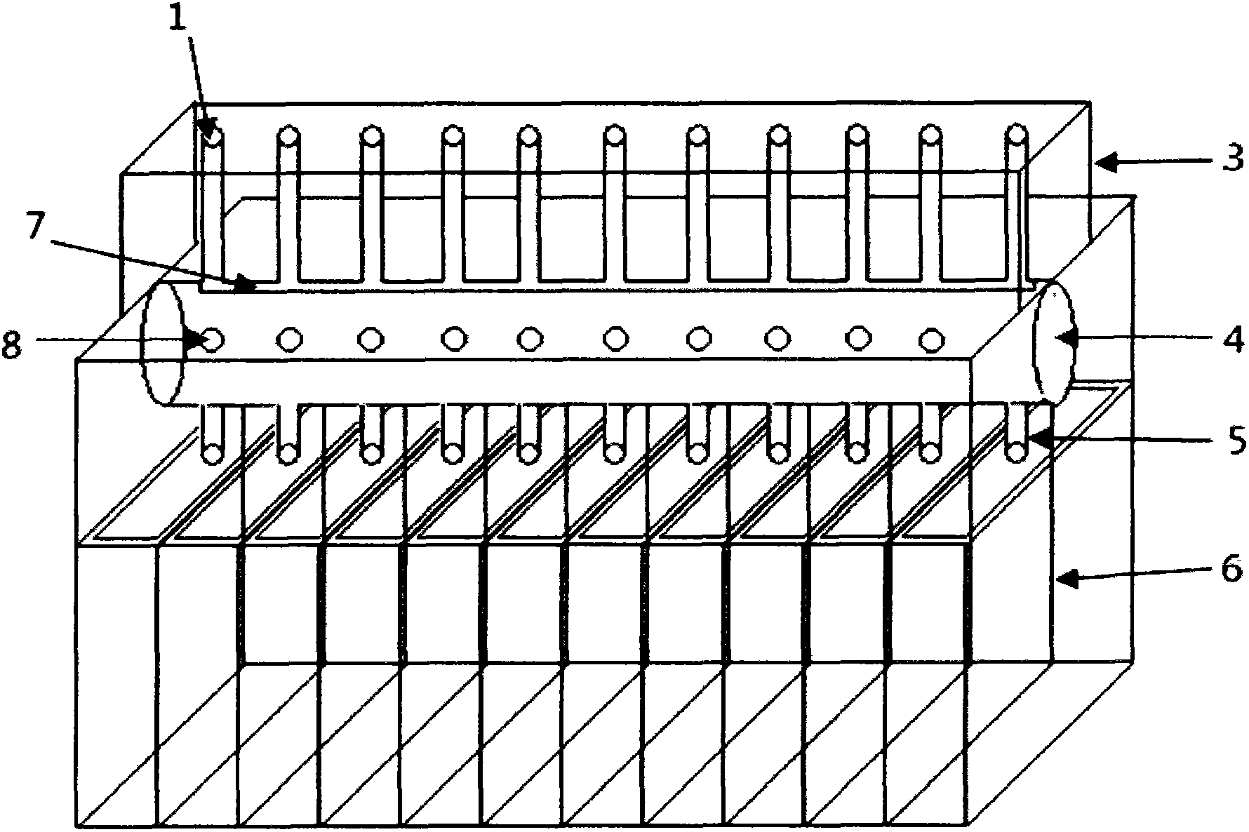
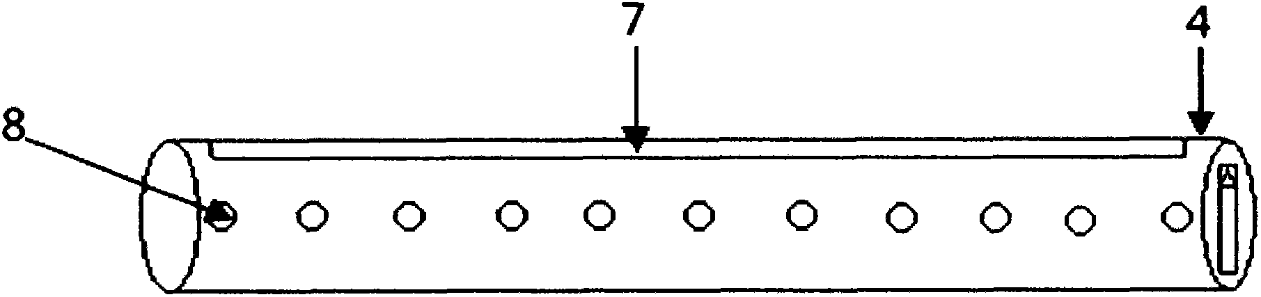
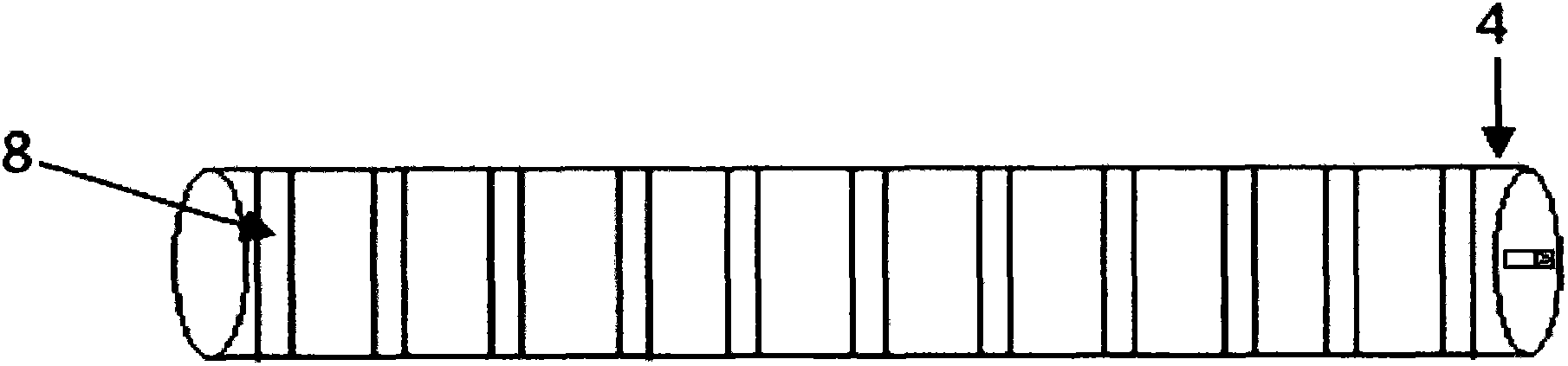
[0023] Such as figure 1 As shown, a rapid sample reagent filling reactor of the present invention that can be used for single reagent determination includes a sample reagent filling device 3, and a multi-channel spacing is set on a transparent plastic plate in the sample reagent filling device 3 Equal sample quantification well 1. At the lower end of the sample quantitative hole 1 is provided a cylindrical and transversely placed rotating shaft 4, a rotating shaft sample communication groove 7 and a rotating shaft sample conducting hole 8 are opened on the rotating shaft 4, and a rotating shaft is opened on the transparent plastic plate below the rotating shaft 4 The end sample via 5 corresponding to the sample via 8. When the rotating shaft sample communication groove 7 is aligned with the lower end of each sample quantitative hole 1, use a common sampler to suck the liquid sample and add the sample from the upper part of a sample quantitative hole 1 in the middle, and the sam...

Embodiment 2

[0026] Such as Figure 4 As shown, a sample reagent rapid filling reactor of the present invention that can be used for dual reagent determination is based on the structure of the sample reagent rapid filling reactor for single reagent determination, in the sample reagent filling device 3 The transparent plastic plate is also provided with multiple-channel reagent quantitative holes 2 with equal spacing corresponding to the sample quantitative holes 1, and the shaft 4 is provided with a shaft reagent through hole 9 correspondingly, and the shaft reagent through hole 9 is connected to the end sample Hole 5 also corresponds.

[0027] When using two reagents to determine biochemical items, first align the sample connecting groove 7 on the rotating shaft 4 with the lower end of each sample quantitative hole 1, and then use a common sampler to absorb a sufficient amount in a sample quantitative hole 1 located in the middle Slowly inject the sample into the sample until each sample qua...


PUM


Abstract

The invention discloses a multichannel liquid sample reagent rapid charging reactor which comprises two parts of a sample reagent charging device and a preset first reagent cuvette. A piece of plastic slab in the sample reagent charging device is provided with multipath sample reagent dosing holes with equal spacing. The holes are corresponding to a rotating shaft sample communication groove on a rotating shaft in the sample reagent charging device. A liquid passes through via holes on the rotating shaft and is introduced into end sample conducting holes. Through rotation of the rotating shaft and a centrifugation method, a sample reagent is rapidly introduced into the preset first reagent colorimetric ware through the end sample via holes. The sample and reagent are mixed and react. And results of each projects are determined through apparatuses. By the adoption of the charging reactor, the range of measured projects is increased. Sample application accuracy is not influenced by precision of a sample injector. The operation process is simple. The charging reactor provided by the invention is especially suitable for human emergency biochemical detection, basic medical unit biochemical detection and animal biochemical detection, and can also be applied in other fields such as immunology, microbiology, molecular biology and the like.

Description

Technical field [0001] The invention relates to the field of medical testing, in particular to a multi-channel liquid sample reagent rapid filling reactor. Background technique [0002] In the field of clinical biomedical testing, biochemical testing occupies a considerable proportion. At present, clinical biochemical tests at home and abroad mainly use fully automatic or semi-automatic biochemical analyzers for testing. The two types of biochemical analyzers are also divided into wet and dry biochemical analyzers based on methodology. However, these instruments mostly use single-channel single-channel and single-channel multi-channel methods for sample and reagent addition. That is, the instrument can only use a sample needle to suck samples into the reaction cup or dry reagent sheet one by one. On the wet biochemical analyzer, one or more reagents are added to the reaction cup one by one. Moreover, the amount of each sample or reagent is not exactly the same, and the driving...

Claims


Application Information

Patent Timeline
IPC IPC(8): G01N35/10
Inventor 张兆麟
Owner 苏州康检云医疗科技有限公司
Why Eureka
Try Eureka