Controlling device and method

A control device and control method technology, applied in the direction of temperature control, adaptive control, electric controller, etc., can solve the problems of detrimental device operation efficiency and longer time

Active Publication Date: 2013-01-16
YAMATAKE HONEYWELL CO LTD
View PDF6 Cites 19 Cited by
  • Summary
  • Abstract
  • Description
  • Claims
  • Application Information

AI Technical Summary

Problems solved by technology

[0003] If the above-mentioned heating device with multiple control loops is used, when the temperature of each control area is raised at the same time, due to the temperature interference between the...

Method used


Image

  • Controlling device and method
  • Controlling device and method
  • Controlling device and method

Examples


Embodiment Construction

[0028] 【Principle of Invention】

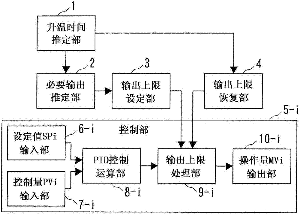
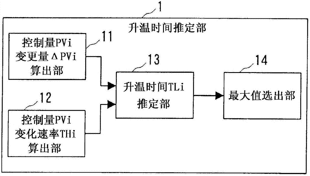
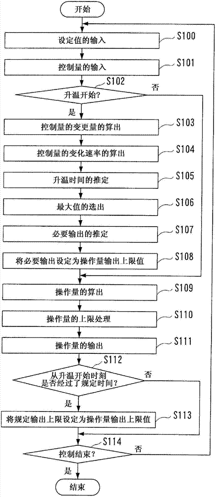
[0029] Preliminary storage of representative temperature rise capabilities (e.g. temperature rise rate at maximum output), estimating the temperature rise rate when reaching an arbitrary output upper limit (manipulated variable MV output upper limit), and calculating the estimation until the end of temperature rise in each control loop The time is basically the same as the output upper limit value. As a result, the temperature rise end time of each control loop is approximately the same, which can be close to the most efficient debugging method.

[0030] With this control method, after the output upper limit is determined once at the start of temperature rise, in principle, there is no need to update the output upper limit in the middle of temperature rise. Therefore, even if there is an abnormality in signal transmission between the PID control operation unit (such as a regulator) and the output upper limit operation unit (such as a host con...


PUM


Abstract

A controlling device comprises: a temperature ramp-up time estimating portion for estimating a required temperature ramp-up time for the controlled quantity in each individual control loop to reach a set point when the operating quantity output upper limit value of each individual control loop has been sent to a specified output upper limit value; a required output estimating portion for estimating, for each individual control loop, a required operating quantity output for the controlled quantity to reach the set point within the temperature ramp-up time; an output upper limit value setting portion for setting, temporarily, the operating quantity output as the operating quantity output upper limit value of the individual control loop; and a controlling portion that is provided for each individual control loop.

Description

technical field [0001] The present invention relates to a control device and a control method of a multi-loop control system with multiple control loops, in particular to control so that when the set value is changed, the time for the control quantity of each control loop to reach the changed set value is basically the same Technology. Background technique [0002] Conventionally, as an example of a heating device having a plurality of control circuits, there is known Figure 5 The oxidation diffusion furnace is shown. A silicon wafer 105 is loaded into the quartz tube 104 in the oxidation diffusion furnace 100 . The temperature sensors 102-1 to 102-3 measure the temperatures PV of the control zones Z1 to Z3 heated by the heaters 103-1 to 103-3, respectively. The regulators 101-1 to 101-3 respectively calculate the operation amount MV so that the temperature PV measured by the temperature sensors 102-1 to 102-3 coincides with the temperature set value SP, and output the op...

Claims


Application Information

Patent Timeline
IPC IPC(8): G05D23/19G05B11/42
CPCG05B13/021G05B11/42G05D23/19G05D23/1919H01L21/67248G05B11/36
Inventor 田中雅人
Owner YAMATAKE HONEYWELL CO LTD
Why Eureka
Try Eureka