RFID-based machine room monitoring device, system and method

A monitoring device and monitoring system technology, applied in the field of communication, can solve the problems of high verification difficulty, high development difficulty and high labor cost, and achieve the effects of reducing data processing pressure, avoiding interface adaptation work, and reducing network data flow.

Inactive Publication Date: 2013-01-16
武汉众邦领创技术有限公司
View PDF4 Cites 7 Cited by
  • Summary
  • Abstract
  • Description
  • Claims
  • Application Information

AI Technical Summary

Problems solved by technology

[0004] If the above-mentioned first implementation method is adopted, there will be the following problems: First, due to the need to manually count, enter, and inventory resources such as equipment and facilities, resulting in high labor costs and low work efficiency; secondly, manual implementation of the above There is a high probability of task error, and there are discrepancies between the data and the real environment; finally, manual processing cannot achieve real-time fixed-point recording and tracking when equipment is moved in and out of the computer room, resulting in difficult verification and other problems
First of all, due to the need to integrate a large number of monitoring systems from different manufacturers, a large amount of interface adaptation work is required, which makes development difficult
Secondly, the monitoring systems of different manufacturers have inconsistent definitions of information, and it is difficult to guarantee the accuracy of information
Finally, manufacturers of non-smart devices (such as DDF racks, ODF racks, cables, etc.) usually cannot provide monitoring methods for monitoring, resulting in smart devices being included in the monitoring range, while non-smart devices cannot be monitored

Method used


Image

  • RFID-based machine room monitoring device, system and method
  • RFID-based machine room monitoring device, system and method
  • RFID-based machine room monitoring device, system and method

Examples


Embodiment Construction

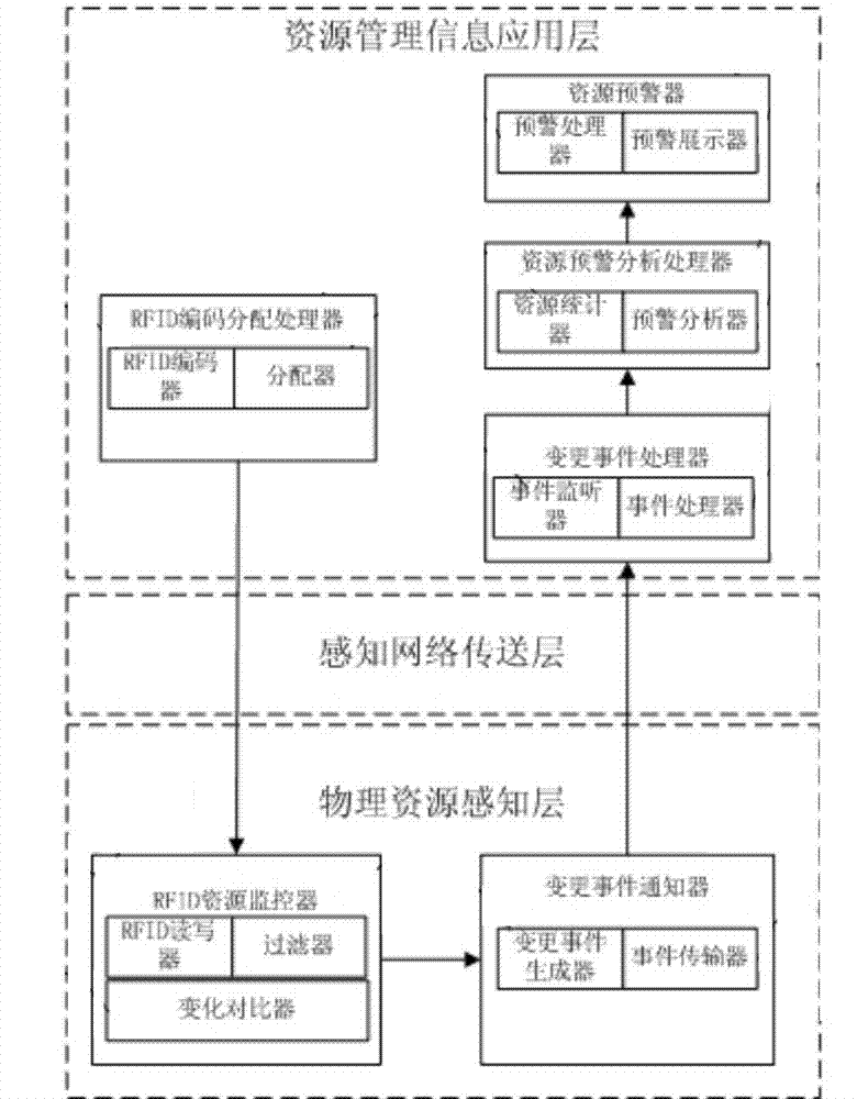
[0035] Figure 5 It is a device structure diagram of an embodiment of the present invention, which includes a passive electronic tag C4 installed on the monitoring device C3, an RFID reader C6 communicating with the passive electronic tag C4, a resource-aware controller C5 and a general controller ; The resource-aware controller C5 is connected to the RFID reader C6 for data interaction, and the resource-aware controller C5 and the general controller are connected for data interaction through a network connection; the number of passive electronic tags C4 is the same as the number of monitoring equipment C3, The number of RFID reader-writers C6 depends on the area range of passive electronic tags, and the number of resource-aware controllers and total controllers depends on the amount of data. The resource-aware controller can be one of a mobile phone, a computer, or a microprocessor, or any combination of them. When the RFID reader reads the status, the RFID reader can be ins...


PUM


Abstract

The invention provides an RFID (Radio Frequency Identification) machine room monitoring device. The device comprises passive e-tags arranged on equipment required to be monitored, RFID readers communicating with the passive e-tags, resource awareness controllers and main controllers, wherein the resource awareness controller is connected with the RFID reader and is also in network connection with the main controller; and the quantity of the passive e-tags is the same as that of the equipment required to be monitored, the quantity of the RFID readers is determined by the area coverage of the passive e-tags, and the quantities of both the resource awareness controllers and the main controllers are determined by data amount. The invention also provides an RFID-based machine room monitoring system and method, the resource awareness controllers are used for processing acquired data and sending the processed data to the main controllers for unified comprehensive processing, so that lots of complex data processing tasks are divided, the data processing pressure of the main controllers is relieved, the network data stream is reduced and errors are avoided.

Description

technical field [0001] The present invention relates to the communication field, in particular to a computer room monitoring device, system and method based on RFID (Radio Frequency Identification, radio frequency identification technology). Background technique [0002] In most computer rooms, it involves monitoring the equipment, operating environment, cables and other resources in the computer room. And these managed devices are provided by different manufacturers and different professions with their own monitoring methods, and their respective monitoring methods have different standards, which makes the computer room monitoring have different monitoring methods and difficult monitoring problems. At the same time, in the monitoring process, there are often problems such as resource value monitoring and physical monitoring being disconnected, equipment life is short, replacement is fast, technical transformation investment is large, maintenance costs are high, and resource...

Claims


Application Information

Patent Timeline
Patent Type & Authority Applications(China)
IPC IPC(8): G06K17/00
Inventor 何双江
Owner 武汉众邦领创技术有限公司
Why Eureka
Try Eureka