Static state device

An equipment, static technology, applied in the direction of organic insulators, transformer/inductor coils/windings/connections, etc., to achieve the effect of good operation efficiency and low moisture adsorption

Inactive Publication Date: 2013-01-16
HITACHI IND EQUIP SYST CO LTD
View PDF7 Cites 0 Cited by
  • Summary
  • Abstract
  • Description
  • Claims
  • Application Information

AI Technical Summary

Problems solved by technology

However, there is no description about preventing the decrease of coil insulation resistance after winding operation by winding polymer film and kraft paper in the main insulation of the coil.

Method used


Image

  • Static state device
  • Static state device
  • Static state device

Examples


Embodiment 1

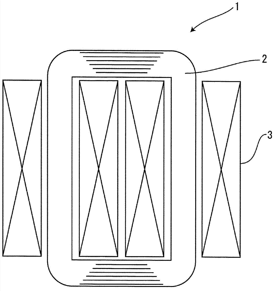
[0033] figure 1 A transformer 1 which is a static device of the present invention is shown, and the transformer 1 is composed of an iron core 2 and a coil 3 . The coil 3 is wound on an iron bobbin described later with a main insulating layer interposed therebetween. Insulating paper made of kraft paper is used for the main insulating layer of the coil 3 of the transformer 1 . Here, a diagram showing a moisture adsorption inhibiting layer provided for the purpose of enhancing the moisture adsorption inhibiting effect of the insulating paper will be described.

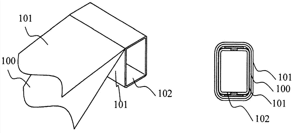
[0034] figure 2 A polymer film 100 constituting a moisture absorption suppressing layer as an insulating material, an insulating paper 101 made of kraft paper as an insulating material, and an iron bobbin 102 for a coil of a static device are shown. The polymer film 100 as the moisture absorption suppression layer is wound on the iron bobbin 102 with insulating paper 101 sandwiched therebetween, and the inner and out...

Embodiment 2

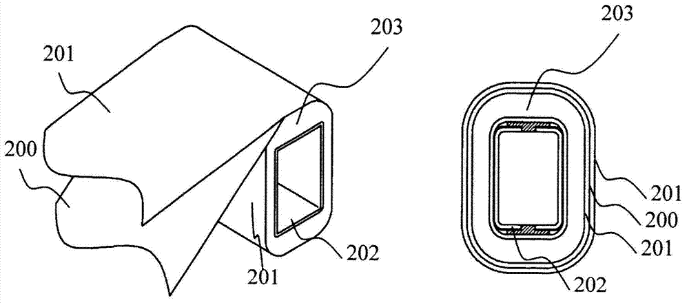
[0036] image 3 A diagram illustrating the provision of a moisture adsorption inhibiting layer on the inner winding of the static device coil of the present invention.

[0037] image 3 Shown is a polymer film 200 constituting a moisture absorption inhibiting layer as an insulating material, an insulating paper 201 made of kraft paper as an insulating material, an iron winding frame 202 of a coil of a static device, and an inner coil wire 203 of the coil. The polymer film 200 serving as a moisture absorption suppressing layer is wound on the inner conductor 203 so as to be sandwiched by the insulating paper 201, and then the outer conductor is wound to complete the coil of the static device. That is, in this embodiment, insulating paper 201 and polymer film 200 having a three-layer structure are interposed between the inner-ring wire and the outer-ring wire.

Embodiment 3

[0039] Figure 4 A diagram illustrating the provision of the moisture adsorption suppression layer on the outermost layer of the static device coil of the present invention.

[0040] Figure 4 Shown is a polymer film 300 constituting a moisture absorption inhibiting layer as an insulating material, an insulating paper 301 made of kraft paper as an insulating material, an iron bobbin 302 of a coil of a static device, and an outer winding 303 of the coil. The polymer film 300 serving as the moisture absorption suppressing layer is wound on the outer winding 303 so as to be sandwiched by the insulating paper 301, and the outer coil wire is wound to complete the coil of the static device. That is, in this embodiment, the insulating paper 301 and the polymer film 300 having a three-layer structure are wound on the outside of the outer coil wire.

[0041] Figure 5 A diagram showing a conventional insulation method for static equipment coils is explained.

[0042] Figure 5 Ins...


PUM


Abstract

The invention provides a static state device. A coil of the static state device is thrown into a drying furnace after being wound to remove the moisture of an insulating paper, and then because the coil is exposed in the air before wiring, so that an insulating resistor is measured before wiring. At this time, for absorbing the moisture, the insulating resistor becomes a resistor below a specified value; and because the coil is thrown into the drying furnace again to remove the moisture, the work labor-hour is increased. When the insulating resistor becomes the resistor below the specified value by absorbing the moisture, the situation may occur that partial discharging causes a short circuit accident, so that it is very dangerous. Therefore, the invention provides the static state device comprising the coil of which the resistance is reduced a little before wiring. The coil is formed by winding conducting wires on a wiring skeleton across a main insulating layer, at least part of overlapping of the above main insulating layer possesses waterproof/moisture-proof macromolecule film to form a laminating structure, and the macromolecule film restrains the moisture absorption of the main insulating layer.

Description

technical field [0001] The present invention relates to techniques for providing static equipment, and in particular to methods of insulating coils. Background technique [0002] As background technology in this technical field, there is Japanese Patent Application Laid-Open No. 11-67552 (Patent Document 1). This gazette describes the content of providing a transformer winding excellent in workability and productivity and a method of manufacturing the same by preventing a reduction in productivity by performing an interlayer insulation paper insertion operation in the process of manufacturing a transformer winding. In addition, there is Japanese Unexamined Patent Publication No. 2001-23831 (Patent Document 2). This bulletin describes the content that, in the winding of a static inductor such as a transformer, by simplifying the insulation structure inside the high-voltage winding opposite to the high-voltage-low voltage winding, the three-dimensional structure surrounded by...

Claims


Application Information

Patent Timeline
Patent Type & Authority Applications(China)
IPC IPC(8): H01F27/30H01F27/32H01B3/18
Inventor 御子柴谅介远藤博之
Owner HITACHI IND EQUIP SYST CO LTD
Why Eureka
Try Eureka