
Dispersed magnetism-conducting block type straight-line switched reluctance motor with single-side stator and rotor with unequal tooth widths

A technology of switched reluctance and magnetic permeable block, which is applied to electric components, electromechanical devices, electrical components, etc., can solve the problems of low utilization rate of iron core materials and low utilization rate of mover slots, and reduce the amount of copper used at the ends. , the effect of simple structure and simple manufacturing process

Active Publication Date: 2015-06-17
SHANDONG UNIV
View PDF4 Cites 0 Cited by
  • Summary
  • Abstract
  • Description
  • Claims
  • Application Information

AI Technical Summary

Problems solved by technology

In addition, the existing linear switched reluctance motor has a low utilization rate of the iron core material due to the long yoke of the stator core, and the phase-to-phase insulation is required in the mover slot, so the utilization rate of the mover slot is low

Method used


Image

  • Dispersed magnetism-conducting block type straight-line switched reluctance motor with single-side stator and rotor with unequal tooth widths
  • Dispersed magnetism-conducting block type straight-line switched reluctance motor with single-side stator and rotor with unequal tooth widths
  • Dispersed magnetism-conducting block type straight-line switched reluctance motor with single-side stator and rotor with unequal tooth widths

Examples


specific Embodiment approach 1

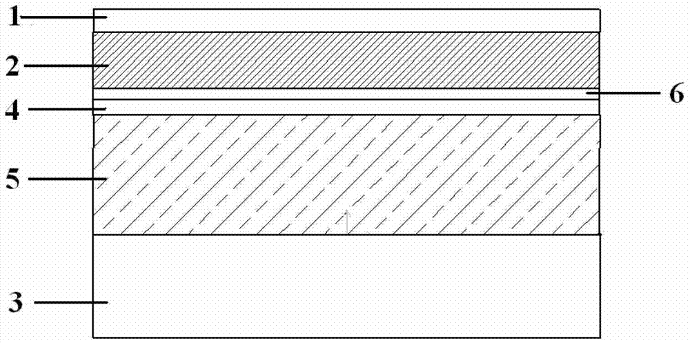
[0027] Such as figure 1 Shown, specific embodiment 1: below in conjunction with figure 1 Embodiment 1 will be described. In this embodiment, the number of phases of the motor is m=3, the number of poles of the mover is Pt=6, and the number of poles of the stator is Ps=4. The blocks 2 are evenly distributed inside the stator frame 1, the bottom of the magnetic permeable block 2 is processed into a dovetail shape so as to be fixed on the stator frame 1, and a mover core 3 is arranged on one side of the stator frame 1, and the stator frame 1 parallel, there is an air gap 6 between the stator base 1 and the mover core 3, the mover core 3 is provided with a mover slot 4, and the mover winding 5 is placed in the mover slot 4, and the mover with a wide tooth width The winding in the mover slot 4 on both sides of the tooth is a coil, and the mover winding 5 enters from the mover slot 4 on one side of the mover tooth with a wider tooth width, passes through the mover slot 4 on the ot...

specific Embodiment approach 2

[0028] Specific implementation mode 2: combine below figure 2Embodiment 2 will be described. The difference between Embodiment 2 and Embodiment 1 is that the number of poles of the stator and mover of the motor is different. In this embodiment, the number of phases of the motor is m=3, the number of poles of the mover is Pt=12, and the number of poles of the stator is Ps=8. The blocks 2 are evenly distributed inside the stator frame 1, the bottom of the magnetic permeable block 2 is processed into a dovetail shape so as to be fixed on the stator frame 1, and a mover core 3 is arranged on one side of the stator frame 1, and the stator frame 1 parallel, there is an air gap 6 between the stator base 1 and the mover core 3, the mover core 3 is provided with a mover slot 4, and the mover winding 5 is placed in the mover slot 4, and the mover with a wide tooth width The winding in the mover slot 4 on both sides of the tooth is a coil, and the mover winding 5 enters from the mover ...


PUM


Abstract

The invention discloses a dispersed magnetism-conducting block type straight-line switched reluctance motor with a single-side stator and a rotor with unequal tooth widths, comprising the stator and the rotor, wherein the stator comprises a stator engine base and a plurality of dispersed magnetism-conducting blocks; the dispersed magnetism-conducting blocks are fixedly arranged in the stator engine base; the stator engine base is provided with a single side and the stator is placed at one side of the rotor; the rotor comprises a rotor iron core; the rotor iron core is provided with rotor teeth, a rotor groove and a rotor yoke part; the tooth widths of the adjacent rotor teeth are unequal; the tooth widths of every other one rotor tooth are the same; and a rotor winding is placed in the rotor groove. The stator disclosed by the invention is the dispersed magnetism-conducting block so that a stator yoke part is omitted; the manufacturing process is simple, the use amount of an iron core material in a process of manufacturing a motor is reduced and the utilization rate of the iron core material is improved; the winding is a concentrated winding and a copper use amount of the end part is reduced; and each rotor groove is internally provided with one set of the winding so that inter-phase insulation is avoided and the utilization rate of the rotor groove is improved.

Description

technical field [0001] The invention relates to a linear switched reluctance motor, in particular to a linear switched reluctance motor with a single-side stator with unequal mover tooth widths and discrete magnetic conduction blocks. Background technique [0002] In the modern industrial production process, most advanced production processes require precise linear motion. To complete the linear motion, the traditional way is to convert the rotary motion into linear motion in the transmission conversion device, but the existence of the transmission conversion device has greatly increased The size of the transmission device is reduced, the reliability and efficiency of the system are reduced, and the equipment cost and maintenance cost are high. In addition, the transmission conversion device will significantly increase the vibration and noise of the transmission system, and reduce the control accuracy and performance of the system. In view of the above reasons, more and more...

Claims


Application Information

Patent Timeline
Patent Type & Authority Patents(China)
IPC IPC(8): H02K41/03
Inventor 王道涵王秀和
Owner SHANDONG UNIV
Learn More