
Double-motor device on horizontal shaft of photoelectric tracking system and tracking and controlling method under synchronous driving

A photoelectric tracking system and synchronous drive technology, applied in the field of capture and tracking, can solve the problems of affecting the accuracy of the tracking frame shaft system, uneven temperature deformation of the horizontal axis, and lowering the resonance frequency of the horizontal axis, so as to strengthen the system stiffness and improve the response. Bandwidth, improve the effect of controlling bandwidth

Inactive Publication Date: 2013-01-16
INST OF OPTICS & ELECTRONICS - CHINESE ACAD OF SCI
View PDF4 Cites 11 Cited by
  • Summary
  • Abstract
  • Description
  • Claims
  • Application Information

AI Technical Summary

Problems solved by technology

However, the traditional single motor drive has the following limitations: on the one hand, the single motor is limited by the output torque; on the other hand, the single motor drive will cause the drive torque at both ends of the horizontal axis to be unbalanced, making the resonance frequency of the horizontal axis lower At the same time, the single motor drive will cause the motor end of the horizontal axis to heat up, causing the horizontal axis to deform due to uneven temperature, affecting the shafting accuracy of the tracking rack

Method used

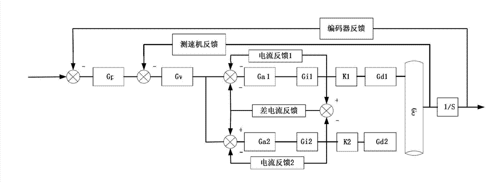
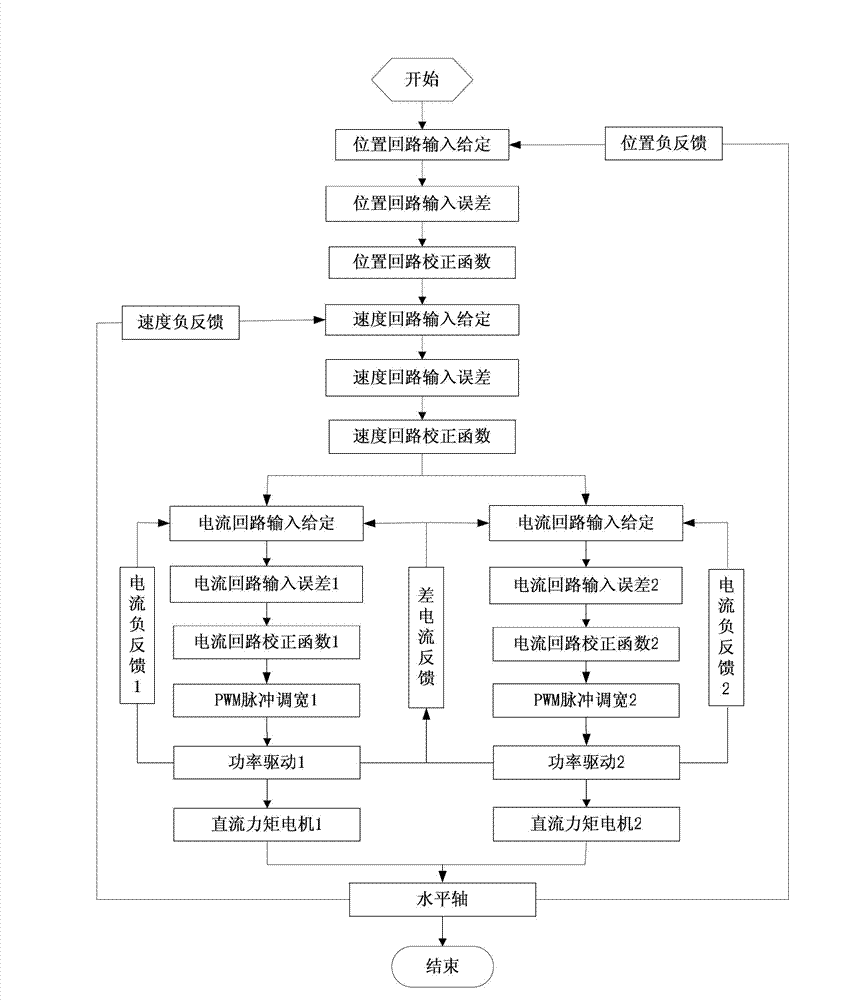

Image

  • Double-motor device on horizontal shaft of photoelectric tracking system and tracking and controlling method under synchronous driving
  • Double-motor device on horizontal shaft of photoelectric tracking system and tracking and controlling method under synchronous driving
  • Double-motor device on horizontal shaft of photoelectric tracking system and tracking and controlling method under synchronous driving

Examples


Embodiment Construction

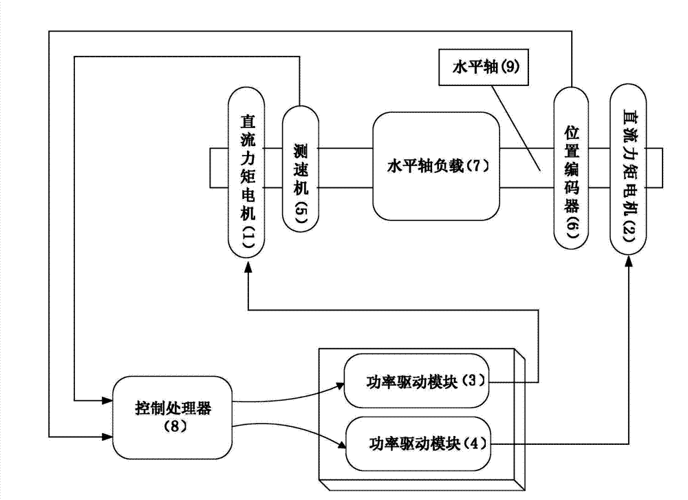
[0027] in figure 1 As shown, the tracking device of the embodiment of the present invention includes: a DC torque motor 1, a DC torque motor 2, a power drive module 3, a power drive module 4, a tachometer 5, a position encoder 6, a horizontal axis load 7 and a control processor 8. ; DC torque motor 1 and tachometer 5 are installed on one side of the horizontal axis; DC torque motor 2 and position encoder 6 are installed on the other side of the horizontal axis; horizontal axis load 7 is installed at the middle position of the horizontal axis, power drive module 3, power The drive module 4 and the control processor 8 are located under the machine.

[0028] in figure 1 As shown, the DC torque motor 1 and the DC torque motor 2 in the real-time example of the present invention are motors of the same model. During installation, since they are installed on both sides of the horizontal axis, the motors must run in the same direction. Therefore, the motor wires of the motors on both sides...


PUM


Abstract

The invention discloses a double-motor device on a horizontal shaft of a photoelectric tracking system and a tracking and controlling method under synchronous driving. The double-motor device comprises direct-current torque motors, a power driving module, a tachometer, a position coder, a horizontal shaft load and a control processor; one of the direct-current torque motors and the tachometer are arranged on one side of the horizontal shaft; the other of the direct-current torque motors and the position coder are arranged on the other side of the horizontal shaft; the horizontal shaft load is arranged in the middle of the horizontal shaft; and the control processor outputs control quantity to the power driving module so as to drive the two motors on the horizontal shaft to operate and work together. According to the invention, the two direct-current torque motors in the same specification can be stably tracked and controlled under the coaxial and synchronous driving, the size of a frame can be reduced under the same load condition, and a larger load output torque can be achieved without reducing the maximum no-load speed; and due to the balanced torque outputs at the two ends of the horizontal shaft, the rigidity of the whole horizontal shaft system is strengthened, so that the closed-loop control bandwidth of the system can be increased.

Description

Technical field [0001] The invention belongs to the field of capture and tracking, and relates to a new tracking device and control method, in particular to a horizontal axis dual-motor device of a photoelectric tracking system and a synchronous drive tracking control method. technical background [0002] With the development of today's science and technology, in the photoelectric tracking measurement system, the demand for tracking measurement distance and the type of measurement target is getting higher and higher. The photoelectric tracking measurement system is constantly developing in the direction of large-scale, that is, the observation aperture is getting larger and larger, and the single unit There are more and more types of system integrated detectors. This means that the requirements for the load torque that the motor can provide are increasing. However, the traditional single motor drive has the following limitations: on the one hand, the single motor is limited by t...

Claims


Application Information

Patent Timeline
Patent Type & Authority Applications(China)
IPC IPC(8): H02P6/04
Inventor 张桐黄永梅杜俊峰
Owner INST OF OPTICS & ELECTRONICS - CHINESE ACAD OF SCI
Learn More