
Sensorless speed regulation controller based on observation method and sensorless speed regulation control method for piezoelectric vibration feeder

A speed control controller, piezoelectric vibration technology, applied in the direction of vibrating conveyor, conveyor control device, conveyor, etc., can solve the problem of feeding speed change and so on

Inactive Publication Date: 2013-01-23
DALIAN UNIV OF TECH
View PDF8 Cites 8 Cited by
  • Summary
  • Abstract
  • Description
  • Claims
  • Application Information

AI Technical Summary

Problems solved by technology

[0005] The purpose of the present invention is to provide a sensorless speed regulation control method and a sensorless speed regulation controller for a piezoelectric vibrating feeder, provide an observation method and a speed regulation control method for the feeding speed and material weight in a resonance state, and solve the existing problems. There is a problem that the feeding speed of the piezoelectric vibrating feeder changes with the increase or decrease of the material

Method used


Image

  • Sensorless speed regulation controller based on observation method and sensorless speed regulation control method for piezoelectric vibration feeder
  • Sensorless speed regulation controller based on observation method and sensorless speed regulation control method for piezoelectric vibration feeder
  • Sensorless speed regulation controller based on observation method and sensorless speed regulation control method for piezoelectric vibration feeder

Examples


Embodiment

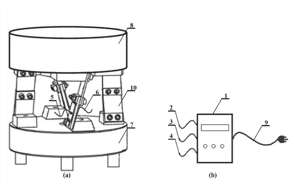
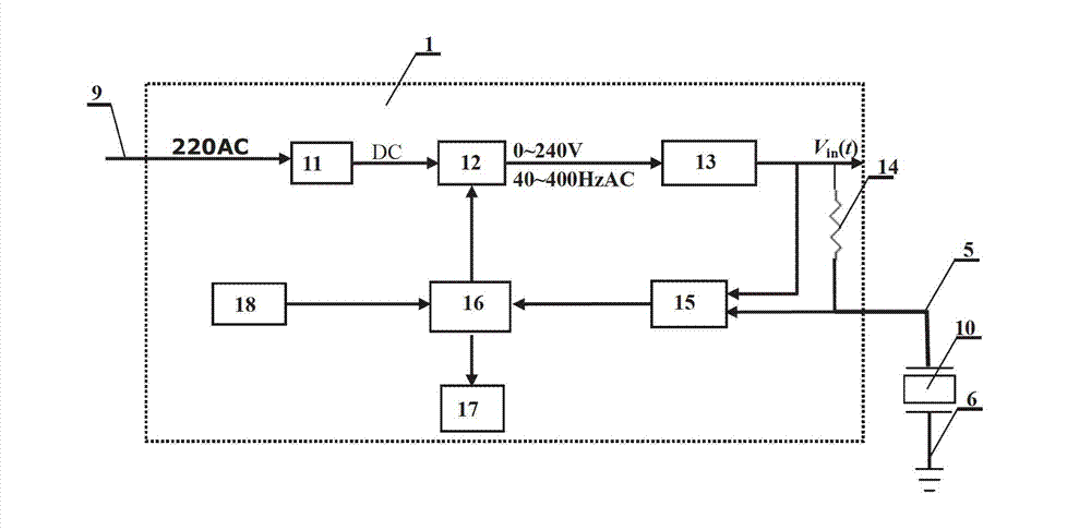
[0048] Embodiment: The theoretical basis of the present invention is that the piezoelectric material has an electromechanical bidirectional reversible piezoelectric effect, and the piezoelectric vibrator is used not only as an exciter to generate vibration, but also as a sensor to feed back vibration velocity information, thereby controlling the feeding speed. Piezoelectric vibrating feeder and sensorless speed controller are attached figure 1 As shown, the piezoelectric vibrators on the four vibrating arms in the piezoelectric vibrating feeder are connected in parallel, which are collectively referred to as piezoelectric vibrators 10. The positive terminal 2 of the driving voltage is connected to the piezoelectric electrode A 5, and the negative terminal 3 of the driving voltage is connected. Connect with the piezoelectric electrode B 6, connect the ground wire 4 with the feeder base 7, insert the mains power line 9 into the 220V / 50Hz mains socket, set the feeding speed throug...


PUM


Abstract

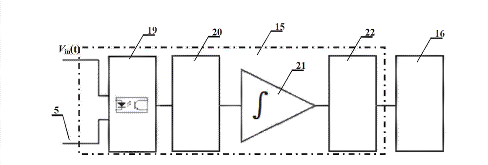
The invention relates to a sensorless speed regulation controller based on an observation method and a sensorless speed regulation control method for a piezoelectric vibration feeder, belonging to the technical field of electromechanical system measurement and control. The sensorless speed regulation control method is characterized in that a frequency domain dynamic model among feeding speed, material weight, piezoelectric vibrator charge amplitude sampling voltage and piezoelectric vibrator driving voltage amplitude is simplified into a static model in a resonance frequency band, and a speed regulation control algorithm which is used for regulating a driving voltage according to the change of the charge amplitude of a piezoelectric vibrator is provided; the provided sensorless controller comprises a rectification filtering voltage stabilizing circuit, an inverter circuit, a driving voltage filter circuit, a sampling resistor, a piezoelectric vibrator charge extracting circuit, a processor, a display panel and a keyboard, wherein the piezoelectric vibrator charge extracting circuit comprises a linear photoelectrical coupling circuit, a low pass filter, an integral circuit and a peak holding circuit. The controller and the method have the advantages and the beneficial effects that a piezoelectric vibrator is used as a vibration exciter and a sensor, the speed regulation control can be conducted without adding an additional amplitude sensor, and when the sensorless speed regulation controller is applied to the existing piezoelectric vibration feeder, the body structure does not need to be changed.

Description

technical field [0001] The invention belongs to the technical field of measurement and control of electromechanical systems, and relates to the control technology of a piezoelectric vibrating feeder for stably conveying parts, especially adopting the observation method to obtain the vibration speed of the feeder from the piezoelectric vibrator element itself, and realize it without an additional vibration sensor A method of closed-loop speed control. Background technique [0002] Vibrating feeders are indispensable equipment in modern automated production assembly systems. The working principle of the piezoelectric vibrating feeder is the inverse piezoelectric effect. When the AC voltage at the resonance frequency is applied to the piezoelectric vibrator, the piezoelectric vibrating arm vibrates to drive the feeder tray to vibrate, so as to achieve the purpose of arranging and conveying materials. The most significant advantage of the piezoelectric vibrating feeder is that ...

Claims


Application Information

Patent Timeline
IPC IPC(8): B65G43/00B65G27/16
Inventor 董维杰马超凡王英俊白凤仙
Owner DALIAN UNIV OF TECH
Learn More