Double-end sealing device for electrodeless lamps

An electrodeless lamp, double-ended technology, applied in cold cathode manufacturing, electrode system manufacturing, discharge tube/lamp manufacturing, etc., can solve problems affecting personal safety, unbalanced force, fracture, etc., to reduce operational technical difficulty, heating Uniform fusion, reducing the effect of operating procedures

Inactive Publication Date: 2013-01-23
常州市武进区牛塘富阳电光源设备厂
View PDF5 Cites 3 Cited by
  • Summary
  • Abstract
  • Description
  • Claims
  • Application Information

AI Technical Summary

Problems solved by technology

At present, in the production of electrodeless lamps, when the lamp tube is sealed, most of the semi-finished lamp tubes are held by hand-held fixtures. After one side is burned and sealed, it is turned over and then burned to the other side. The output is small, the labor intensity is high, and the production efficiency is low. This problem has become a problem. The primary issue affecting the development of the electrodeless lamp industry
In the prior art, such as CN201020119815.9 "Bridging Fire Head of Electrodeless Lamp Bridge Machine" includes an appliance rack with a group of nozzles; in this appliance rack, two semicircular frames are hinged by a hinge shaft to form a In the open closed ring, the above-mentioned group of nozzles are equidistantly arranged on the inner side of the frame body, and the airflow injection direction of all nozzles is aligned with the central part of the closed ring. However, this technology cannot ensure that the two ends of the lamp tube are heated and stressed at the same time. It is unbalanced, and the heating quality is not easy to be guaranteed. During the sealing process, it is easy to break due to stress or cause breakage in future use due to the existence of stress, which may easily cause unnecessary property loss or affect personal safety.

Method used


Image

  • Double-end sealing device for electrodeless lamps

Examples


Embodiment 1

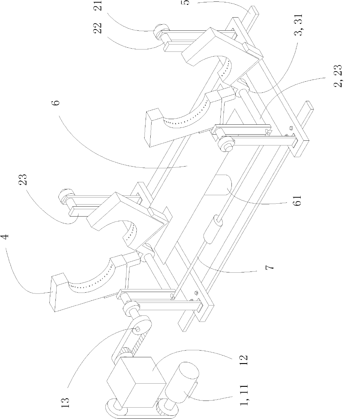
[0019] combine figure 1 , the present invention has a drive device 1, a transmission device 2, a control block 3 and an annular fire head 4; the drive device 1 is composed of a servo motor 11, a reducer 12 and a position sensing device 13, the position sensing device 13 is an infrared sensing device, and the ring fire head 4 It is two open fire heads, two ring fire heads 4 are arranged on the same plane, the rotation axes of the two ring fire heads 4 are parallel, the lower end of the ring fire head 4 is provided with a control block 3, and the transmission device 2 has bearing frames arranged on both sides of the ring fire head 4 21. There are two bearing frames 21 on each side, respectively corresponding to the annular fire head 4, and a rotating shaft 22 is installed on each bearing frame 21, and the rotating shaft 22 is coaxially arranged with the corresponding ring fire head 4, and the rotating shaft 22 is fixedly connected to the swing crank arm 23. The other end of the ...


PUM


Abstract

The invention discloses a double-end sealing device for electrodeless lamps, which comprises annular fire heads, wherein the annular fire heads are two open fire heads, the two annular fire heads are arranged on a same plane, rotating axes of the two annular fire heads are parallel, the lower ends of the annular fire heads are provided with a control block, the control block is connected with a transmission device, the transmission device is connected with a driving device, and the driving device drives the two annular fire heads to synchronously rotate through the transmission device. According to the invention, in the processes of sealing and heating electrodeless lamp tubes, the two ends of products are heated and sealed synchronously, so that the fusion is uniform, the stress is significantly reduced, the unqualified rate is low, the rate of finished products is improved, the production efficiency is increased by 3-5 times, the labor is reduced, the difficulty of operation techniques is reduced, and the operation process of the operating personnel at a high temperature is reduced, therefore, the device is applicable to the processing of electrodeless lamp tubes in various specifications and sizes, and reduces the cost of production.

Description

technical field [0001] The invention relates to a sealing device for an electrodeless lamp, in particular to a double-end sealing device for an electrodeless lamp. Background technique [0002] Promise Light is the abbreviation of Promise Light high-frequency plasma discharge electrodeless lamp. A new type of light source with high luminous efficiency, long life, and high color rendering in the future. At present, in the production of electrodeless lamps, when the lamp tube is sealed, most of the semi-finished lamp tubes are held by hand-held fixtures. After one side is burned and sealed, it is turned over and then burned to the other side. The output is small, the labor intensity is high, and the production efficiency is low. This problem has become a problem. The primary issue affecting the development of the electrodeless lamp industry. In the prior art, such as CN201020119815.9 "Bridging Fire Head of Electrodeless Lamp Bridge Machine" includes an appliance rack with a ...

Claims


Application Information

Patent Timeline
Patent Type & Authority Applications(China)
IPC IPC(8): C03B23/045C03B23/057H01J9/26
CPCY02P40/57
Inventor 冯仁富
Owner 常州市武进区牛塘富阳电光源设备厂
Why Eureka
Try Eureka