

Variable compression ratio device with self-locking structure
A technology of self-locking structure and compression ratio, which is applied in engine control, machine/engine, mechanical equipment, etc., can solve the problem of inability to adjust the compression ratio of multi-cylinder engines synchronously, unable to be put into large-scale applications, and unable to detect piston strokes, etc. problems, to achieve the effect of convenient adjustment and control, small hydraulic drive torque, and avoid damage
- Summary
- Abstract
- Description
- Claims
- Application Information
AI Technical Summary
Problems solved by technology
Method used
Image

Examples
Embodiment 1
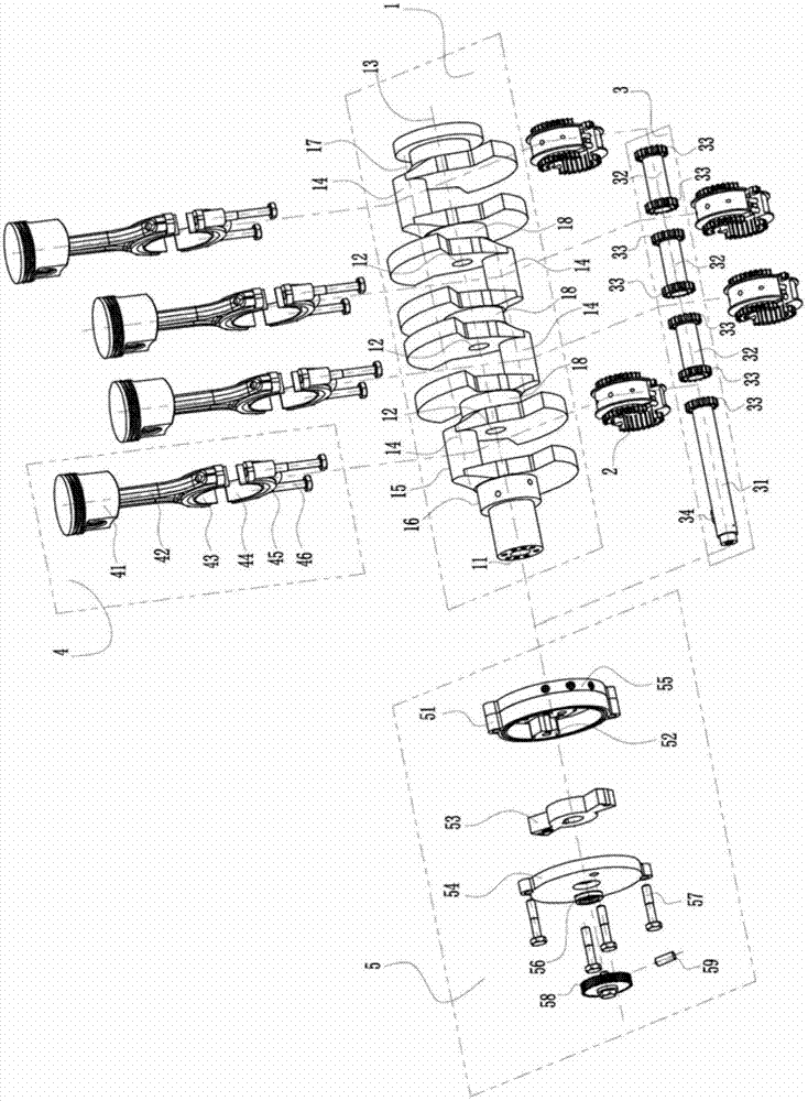
[0074] See first figure 1 , figure 1 Shown is the explosion diagram of the first scheme of the variable compression ratio device with self-locking structure of the present invention. The variable compression ratio device is installed on the crankshaft 1 and the piston connecting rod assembly 4 of the engine, which includes: the eccentric bushing assembly 2, the transmission shaft and the gear assembly 3, the driver assembly 5 and the control valve assembly into 6 (see Figure 10 ).
[0075] Described crankshaft 1 is provided with a main journal 16 that is positioned at the end, several main journals 18 and some connecting rod journals 14, and the outer circumference of this connecting rod journal 14 forms the connecting rod journal outer cylindrical surface 15; Center, offer a cylindrical hole 11 in the main journal 16, offer some cylindrical holes 12 in some main journals 18, the center line of this cylindrical hole 11 and some garden column holes 12 coincides completely w...
Embodiment 2
[0153] Figure 11 , Figure 12 and Figure 13 It is a schematic diagram of embodiment two, and embodiment two is generally the same as embodiment one, and the difference is that the eccentric shaft sleeve assembly 2 of embodiment one is replaced by an eccentric shaft sleeve assembly 2'. The gear 28 on the two ends of the eccentric bushing assembly 2' is a fan-shaped internal gear with a rotation angle of less than 360 degrees, see Figure 13 , and form an internal mesh with the transmission gear 33 on the main transmission shaft 31 and the transmission shaft 32 .
[0154] When the compression ratio needs to be increased or decreased, the rotation direction of the rotating impeller 53 is opposite to that of the first embodiment.
[0155] In order to provide sufficient stroke change, the rotation angle of the rotating impeller 53 needs to be larger, and the parameters of the meshing gear pair (33, 28) need to be modified accordingly. If necessary, a drive consisting of a sing...
Embodiment 3
[0158] Figure 14 , Figure 15 and Figure 16 It is a schematic diagram of embodiment three, which is generally the same as embodiment one, except that the drive shaft and gear assembly 3 of embodiment one are replaced with drive sleeves and gear assembly 3'. The transmission sleeve and gear assembly 3' includes several transmission sleeves 36 and several transmission gears 361; The outer peripheries of the main journals 16, 18 of the crankshaft 1 rotate around the crankshaft center line 13; the transmission gears 361 are internal gears and are respectively fixed on the two ends of each transmission sleeve 36, and the transmission gears 361 are fan-shaped with a rotation angle of less than 360 degrees The internal gear can be directly provided at the end of the drive sleeve 36, and the gear 361 and the gears 20 on both ends of each eccentric bushing assembly 2 form an internal mesh one by one (see Figure 16 ). The front cover 54, the rear cover 55, the casing 51, the fixe...
PUM
 Abstract
Description
Claims
Application Information