Disc type molecular pump

A molecular pump and disc technology, applied in the field of molecular pumps, can solve the problems of chipping damage and static vane damage, and achieve the effect of improving the pumping rate and wide application prospects.

Active Publication Date: 2013-01-23
李晨 +1
View PDF5 Cites 5 Cited by
  • Summary
  • Abstract
  • Description
  • Claims
  • Application Information

AI Technical Summary

Problems solved by technology

Since the high-speed rotating blades are only suitable for working in the state of molecular flow of gas, once they are impacted by a large flow of gas, the blades are prone to damage due to the material and structural shape of the blade, and the damage to the stator blades is also involved.

Method used


Image

  • Disc type molecular pump
  • Disc type molecular pump
  • Disc type molecular pump

Examples


Embodiment Construction

[0013] The structure of the present invention will be described in further detail below in conjunction with the accompanying drawings.

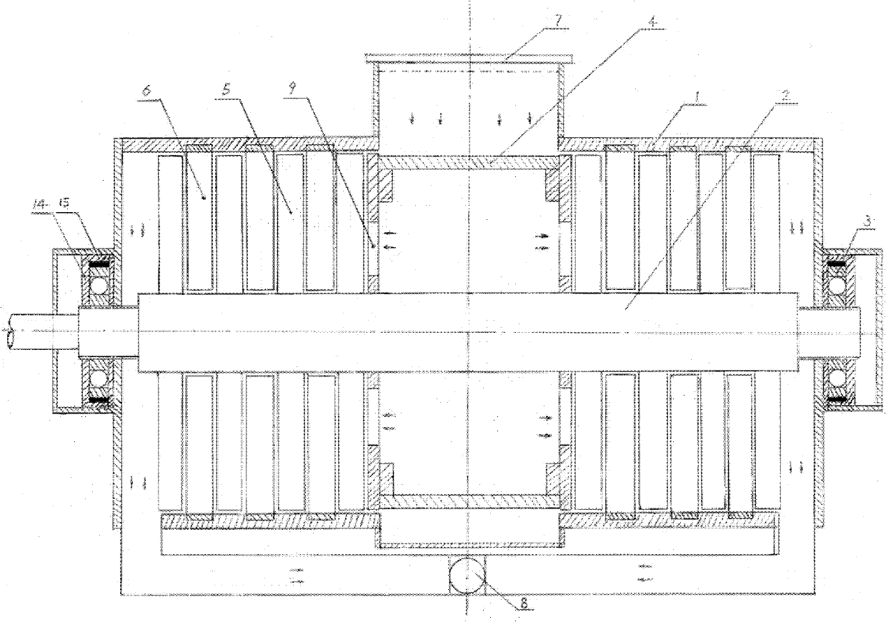
[0014] The pumping process of the disc molecular pump of the present invention is as follows: the gas entering the suction port first passes through the high-speed rotating squirrel-cage gas-gathering and guiding device, and then guides the gas into the left and right coaxially installed multi-stage dynamic and static circles. The air pumping unit composed of disks implements the dragging, transporting and compressing functions of gas molecules, so that the gas molecules make directional movement, and finally lead to the gas discharge port, and are taken away by the fore-stage vacuum pump.

[0015] see figure 1 , (1) is the pump body. (2) is rotating shaft. (3) is the bearing of bearing rotating shaft (2). (14) is bearing seat. (15) is shock pad, is used for reducing the vibration and the noise that the rotor of high-speed rotation brings...


PUM


Abstract

The invention discloses a disc type molecular pump, which comprises a motive disc, a static disc and a pump body. The disc type molecular pump is characterized in that a radial rectangular or a ladder-shaped air flue is arranged on the motive disc and the static disc with certain thicknesses, so as to allow gas molecules on the discs to communicate; and slant angles between the two radial sides of the air flue and the horizontal planes of the discs can be changed from 0 to 180 degrees respectively. In the two radial sides of the air flue on the motive disc and the static disc, as one side mainly for delivering gas molecules, the inclination direction of the two is opposite, while the other side is subject to associating with the delivery of the gas molecules. An air exhaust unit comprising multi-stage motive discs and static discs drives the gas molecules to move in the fixed direction, so as to drag, deliver and compress the gas molecules, thereby performing air exhaust. The disc type molecular pump has the characteristics of simple structure, convenience in manufacturing and processing, large mechanical strength and high resistance against large flow gas impact, and can be widely applied to the medium and high vacuum fields.

Description

technical field [0001] The invention relates to a molecular pump, in particular to a disc type molecular pump. Background technique [0002] At present, the turbomolecular pump widely used to obtain medium and high vacuum, its pumping unit is composed of a series of moving impellers and stationary impellers arranged alternately. The inclination directions of the blades and the stator blades are opposite to each other. When the moving impeller fixed on the rotor rotates at high speed around the stationary impeller fixed on the pump body, the high-speed rotating moving blade transfers the momentum to the gas molecules, which greatly increases the collision between the gas molecules and the moving blades and the stationary blades Opportunity to make gas molecules move in a directional manner to achieve the purpose of pumping. Since the high-speed rotating blades are only suitable for working in the state of molecular flow of gas, once they are impacted by a large flow of gas,...

Claims


Application Information

Patent Timeline
Patent Type & Authority Applications(China)
IPC IPC(8): F04D19/04
CPCF04D29/321F04D19/042
Inventor 李晨胡忠浩
Owner 李晨
Why Eureka
Try Eureka