Header pipe and heat exchanger

A technology of collecting tubes and flat tubes, applied in the field of collecting tubes, can solve the problems of surface rust and corrosion, affecting the discharge of condensed water, mechanical deformation of heat exchangers, etc. The effect of heat exchange efficiency

Active Publication Date: 2013-01-23
SANHUA HANGZHOU MICRO CHANNEL HEAT EXCHANGER
View PDF5 Cites 8 Cited by
  • Summary
  • Abstract
  • Description
  • Claims
  • Application Information

AI Technical Summary

Problems solved by technology

[0006] However, the condensed water is formed in the upper, middle and lower parts of the heat exchanger, and the condensed water flowing down from the upper part of the heat exchanger will collect in the middle and lower parts of the heat exchanger, especially the bottom, and the condensed water will not be discharged in time The problem
If the wind speed outside the heat exchanger is high, the condensed water collected in the middle and lower part of the heat exchanger will be blown away instead of falling into the drain pan, and the condensed water flying away from the drain pan will fall to other components. Metal surfaces such as fan hoods, making the surface rusty and corroded
In addition, when the temperature of the refrigerant in the heat exchanger is lower than the freezing point, if the condensed water collects and cannot be discharged in time, it will freeze on the surface of the heat exchanger, and the frozen layer will continue to accumulate, which will further affect the discharge of condensed water
At the same time, the icing layer will also affect the heat transfer effect of the heat exchanger. The expansion of the icing layer may cause mechanical deformation or even damage of the heat exchanger.

Method used


Image

  • Header pipe and heat exchanger
  • Header pipe and heat exchanger
  • Header pipe and heat exchanger

Examples


Embodiment Construction

[0034] The core of the present invention is to provide a header for the heat exchanger, which can accelerate the discharge speed of the condensed water of the heat exchanger. Another core of the present invention is to provide a heat exchanger comprising the above header.

[0035] In order to enable those skilled in the art to better understand the solution of the present invention, the present invention will be further described in detail below in conjunction with the accompanying drawings and specific embodiments.

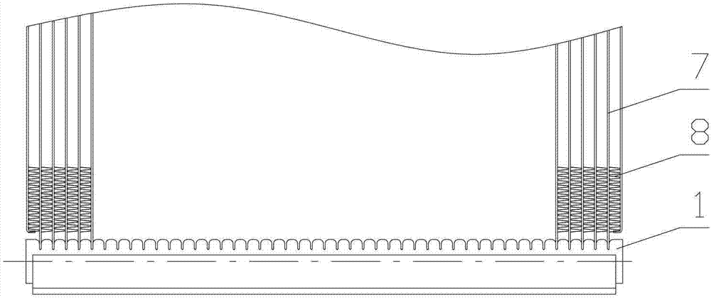
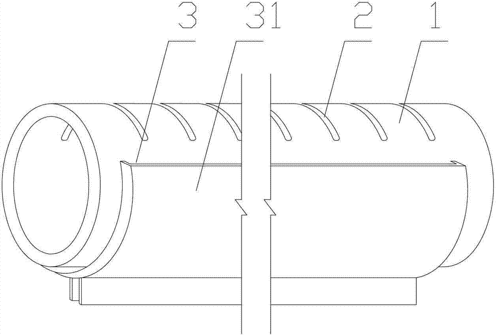
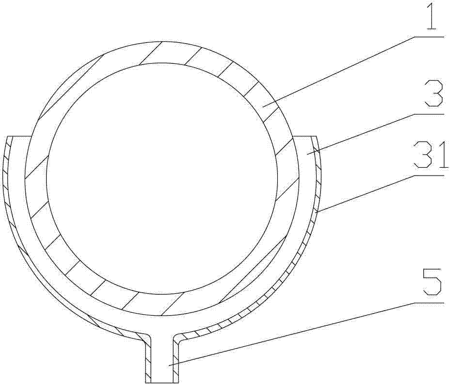
[0036] Please refer to Figure 1 to Figure 3 , figure 1 It is a schematic structural diagram of the first embodiment of the heat exchanger provided in the embodiment of the present invention, figure 2 for figure 1 Shown is a perspective view of a first embodiment of a header of the present invention, image 3 for figure 2 Side cutaway view of header shown.

[0037] In this embodiment, the present invention provides a collector, which includes a pipe main ...


PUM


Abstract

The invention discloses a header pipe which comprises a pipe main body; the upper part of the pipe main body is provided with a flat pipe groove; the outer side of the lower part of the pipe main body is provided with a capillary groove wall; a clearance between the inner wall surface of the capillary groove wall and the outer wall surface of the pipe main body forms a capillary groove; the lower end of the capillary groove is provided with a water outlet communicated with the capillary groove; two ends of the wall of the capillary groove are provided with end parts which are matched with the outer wall surface of the pipe main body; condensed water flows down from the upper part of the heat exchanger, and the capillary groove can generate the capillary phenomenon when the condensed water flows through the outer wall of the pipe main body and is in contact with the capillary groove; under the effect of the capillary phenomenon, the condensed water is exhausted out through the water outlet rapidly, and the header pipe with the structure accelerates the exhaust speed of the condensation water; and the improvement of the exhaust speed of the condensation water can effectively prevent problems caused if the condensed water is not exhausted in time. The invention also discloses a heat exchanger comprising the header pipe.

Description

technical field [0001] The invention relates to the technical field of heat exchange, in particular to a header. In addition, the present invention also relates to a heat exchanger comprising the above-mentioned header. Background technique [0002] Heat exchangers are common equipment in chemical, petroleum, food and many other industrial sectors, and play an important role in production. [0003] A heat exchanger is an exchange device that transfers part of the heat of the hot fluid to the cold fluid so that the temperature of the fluid reaches the target heat specified in the process, also known as a heat exchanger. In practical applications, heat exchangers can be used as heaters, coolers, condensers or evaporators, etc., and heat exchangers are widely used and of various types. [0004] A heat exchanger usually includes at least headers, flat tubes and fins. There are several parallel flat pipe grooves on the collecting pipe, several flat pipes are arranged between t...

Claims


Application Information

Patent Timeline
Patent Type & Authority Applications(China)
IPC IPC(8): F28F17/00F28F9/02F25B39/00
Inventor 王艳红董洪洲李艳星
Owner SANHUA HANGZHOU MICRO CHANNEL HEAT EXCHANGER
Why Eureka
Try Eureka