Automatic detecting device of screw rod straightness and applications thereof

An automatic detection device and straightness technology, which is applied in the direction of measuring devices, optical devices, instruments, etc., can solve the problems of poor detection accuracy and slow detection speed, and achieve the effect of realizing automation, ensuring safety and accurate measurement results

Active Publication Date: 2013-01-23
NANJING KANGNI MECHANICAL & ELECTRICAL +1
View PDF7 Cites 30 Cited by
  • Summary
  • Abstract
  • Description
  • Claims
  • Application Information

AI Technical Summary

Problems solved by technology

[0006] Aiming at the problems of slow detection speed and poor detection accuracy in the existing manual detection method for the straightness of the screw rod, the present invention provides an automatic detection device for the straightness of the screw rod and its application, which can fully automatically detect the straightness of the screw rod. The straightness of the screw with the spiral groove feature is tested to realize the automation of the straightness detection of the screw, the detection process is fast, the result is accurate, and the quality of product detection is improved.

Method used


Image

  • Automatic detecting device of screw rod straightness and applications thereof
  • Automatic detecting device of screw rod straightness and applications thereof
  • Automatic detecting device of screw rod straightness and applications thereof

Examples


Embodiment 1

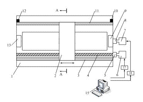
[0034] Such as figure 1 , figure 2 , image 3 As shown, a screw rod straightness automatic detection device includes a base 1 and a laser displacement sensor 16. There are 1-4 laser displacement sensors 16, and 4 are preferably selected in this embodiment, and also include a mobile measuring table 2, a measuring The table motion control system and the screw mandrel rotation system to be measured, the laser displacement sensor 16 is installed on the mobile measuring platform 2, and the laser displacement sensor 16 is connected with the industrial computer 15 through the data transmission line;

[0035] The motion control system of the measuring table comprises a first moving guide rail 3, a second moving guide rail 11, a ball screw 4, a first shaft coupling 5, a first servo motor 6 and a first servo controller 17; the first moving guide rail 3 and The second moving guide rail 11 is arranged on the base 1 in parallel; the ball screw 4 is parallel to the first moving guide ra...

Embodiment 2

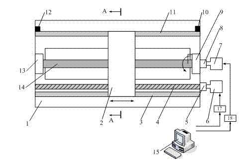
[0042] Such as figure 1 , figure 2 , Figure 4 As shown, with embodiment 1, the difference is that there is one laser displacement sensor 16, then after a scanning measurement, the second servo motor 7 automatically controls the rotation of the measured screw mandrel 14, and is respectively positioned as figure 2 On the positions a, b, c, and d of the screw mandrel 14 to be tested according to the formula, scanning measurement is carried out respectively. After the data of the four positions are measured, the industrial computer 15 performs data processing and fits to obtain the straightness of the measured screw rod 14, and finally gives an evaluation conclusion on whether it is qualified or not.

Embodiment 3

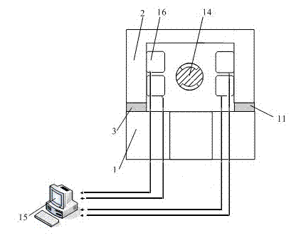
[0044] Such as figure 1 , figure 2 , Figure 5 As shown, with embodiment 1, the difference is that there are two laser displacement sensors 16, then after a scanning measurement, the second servo motor 7 automatically controls the rotation of the measured screw mandrel 14, from the original as Figure 5 The a, b positions of the tested screw mandrel 14 are transferred to the c, d positions, and then scanning measurement is performed. After the data of the four positions are measured, the industrial computer 15 performs data processing and fits to obtain the straightness of the measured screw rod 14, and finally gives an evaluation conclusion on whether it is qualified or not.


PUM


Abstract

The invention discloses an automatic detecting device of screw rod straightness and applications thereof, and belongs to the field of automatic straightness detecting devices. The automatic detecting device of screw rod straightness comprises a base platform, a laser displacement sensor, a moving measuring platform, a measuring platform control system and a to-be-measured screw rod rotary system, wherein the laser displacement sensor is installed on the moving measuring platform and is connected with an industrial computer through a data transmission line; the measuring platform moving control system comprises a first moving guide rail, a second moving guide rail, a rolling ball screw rod, a first coupling, a first servo motor and a first servo controller. According to the invention, straightness of a screw rod with spiral groove characteristics can be detected automatically, and the automatic detecting device has the advantages of rapid detection process, accurate results and low product detection cost.

Description

technical field [0001] The invention belongs to the field of straightness automatic detection devices, and more specifically relates to a screw rod straightness automatic detection device and its application. Background technique [0002] Screw rods are widely used and extremely important parts in the machinery industry. They are generally used in transmission mechanisms to convert rotary motion into linear motion (or convert linear motion to rotary motion) and transmit power, such as in CNC machine tools, rail vehicles in the door system. In addition to transmitting motion and power, the screw rod must also ensure a certain transmission accuracy to achieve smooth motion, especially in precision machine tools, which depends on the size and shape of the screw rod processing. Among the many factors affecting the smoothness of the screw rod movement, the straightness of the screw rod is the most important factor, and it is also the main parameter to evaluate the processing qua...

Claims


Application Information

Patent Timeline
Patent Type & Authority Applications(China)
IPC IPC(8): G01B11/27
Inventor 许有熊朱松青史翔韩亚丽陈茹雯郝飞
Owner NANJING KANGNI MECHANICAL & ELECTRICAL
Why Eureka
Try Eureka