Sampling system for automatically identifying samples and sampling method for sampling system
A sampling system and sample technology, applied in the direction of analyzing materials, instruments, etc., can solve the problems that manual sampling cannot automatically inject multiple sample types, single, increase trouble and cost, etc., to prevent inaccurate test results of instruments, operability Strong, low-cost effects
- Summary
- Abstract
- Description
- Claims
- Application Information
AI Technical Summary
Problems solved by technology
Method used
Image

Examples
Embodiment 1
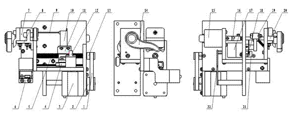
[0033] Such as figure 1 As shown, when the sampling rack 6 is in use, it will automatically return to the initial state and initial position. The process is as follows: the stepping motor 3 drives the screw rod 5 to rotate through the rotation of the synchronous belt 1, and the sampling arm 10 is installed on the rolling linear guide rail 4 and connected with the screw rod 5. The rod 5 is connected. When the screw rod 5 rotates, the sampling arm 10 moves linearly, and the sampling needle 9 is fixed on the sampling arm 10 and inserted into the sampling nozzle 7. When sampling is required, the stepper motor 3 rotates to drive the screw rod. 5 rotate, so that the sampling arm 10 drives the sampling needle 9 to move in the sampling nozzle 7, and the first optocoupler 12 detects the initial position to control the movement amount of the sampling needle 9 during the movement, thus realizing the sampling process.
Embodiment 2
[0035] The deceleration stepper motor 17 drives the rotary cam 18 to rotate, and the swing roller 19 is placed on the rotary cam 18 and connected with the rotating shaft 20 . The rotating shaft 20 is fixed with the sample type detection arm 14 and connected with the rotary encoder 15 through a coupling 16 . When the rotary cam 18 rotates, the swing roller 19 swings within a certain angle so that the rotating shaft 20 drives the sample type detection arm 14 to swing to detect the sample type, and when the sample type detection arm 14 detects the sample, the rotary encoder 15 is rotated by one Angle, the rotary encoder 15 recognizes the angle pulse signal reading and sends the reading to the main control board 22. At this time, the main control board 22 reads the angle reading for comparison to determine the type of the sample. This process completes the sample type detection.
Embodiment 3
[0037] Firstly, the stepper motor 3 rotates so that the first optical coupler 12 just detects the light blocking sheet 11. At this time, the sampling needle 9 is inserted into the sampling nozzle 7, and this state is the "0" position of the sampling part. At the same time, the sample type identification part decelerates the stepper motor 17 to rotate, so that the second light couple 21 cannot detect the light blocking sheet 11. This state is the sample type detection arm 14 "0" position. At this time, the sample type detection arm 14 is at the sampling interface. 7 below. Then the stepper motor 3 rotates so that the sampling needle 9 stretches out of the sampling nozzle 7, and then the sample type identification part decelerates the stepper motor 17 to rotate so that the sample type detection arm 14 touches the sampling needle 9, because the sample type detection arm 14 and the rotary encoder 15 are connected, and the rotation of the rotary encoder 15 will generate several pul...
PUM
 Abstract
Description
Claims
Application Information
 - R&D
- Intellectual Property
- Life Sciences
- Materials
- Tech Scout
- Unparalleled Data Quality
- Higher Quality Content
- 60% Fewer Hallucinations
Browse by: Latest US Patents, China's latest patents, Technical Efficacy Thesaurus, Application Domain, Technology Topic, Popular Technical Reports.
© 2025 PatSnap. All rights reserved.Legal|Privacy policy|Modern Slavery Act Transparency Statement|Sitemap|About US| Contact US: help@patsnap.com