Conductive loop structure of switch device

A technology of conductive circuit and switchgear, applied in the direction of protection switch operation/release mechanism, protection switch terminal/connection, etc., can solve the problems that have not been seen in technical enlightenment, shorten the breaking time, improve the current limiting performance, and improve the breaking capacity Effect

Active Publication Date: 2013-12-11
CHANGSHU SWITCHGEAR MFG CO LTD (FORMER CHANGSHU SWITCHGEAR PLANT)
View PDF3 Cites 0 Cited by
  • Summary
  • Abstract
  • Description
  • Claims
  • Application Information

AI Technical Summary

Problems solved by technology

However, when the movable guide rod 6 moves to the top of the connecting guide rod 41, the first and second section conductors 411, 412 will generate downward suction force on the movable guide rod 6, thereby hindering the movement of the movable guide rod. The continued movement of 6 to the opening direction reduces the current limiting capacity of the switching device, that is, the circuit breaker
In addition, under this structure, since the first and second sections 411, 412 are located above the fixed contact 8 fixed on the third section 413, the installation space of the arc extinguishing mechanism is occupied, so that the switching device such as a circuit breaker is disconnected. The ability to improve is very limited
[0010] The deficiencies of the above-mentioned prior art can be summarized as the following two aspects: one is that the positive magnetic field in the contact arc extinguishing system area of ​​the switchgear is relatively weak, so Affects the driving force or driving effect or driving speed of the movable guide rod in the direction away from the fixed guide rod, so that when encountering a fault current caused by a situation such as an overload or a short circuit, it can be When the moving contact breaks the fault current, it loses instantaneous quickness, which seriously affects the breaking capacity (current limiting capacity) of the switchgear, that is, the circuit breaker; secondly, because the volume of the conductive loop structure in the height direction of the whole switchgear is relatively Larger, thus occupying the proper space of the arc extinguishing mechanism, thus affecting the arc extinguishing ability of the switchgear such as a circuit breaker, and making it difficult to improve the breaking capacity
[0011] In view of the above, the applicant has done a more extensive and in-depth literature search, but all the patents and non-patent literatures that have been disclosed so far have not been found to be eliminated. For the aforementioned lack of technical enlightenment, the applicant has made a beneficial design for this reason, and has formed the technical scheme that will be introduced below

Method used


Image

  • Conductive loop structure of switch device
  • Conductive loop structure of switch device
  • Conductive loop structure of switch device

Examples


Embodiment 1

[0040] See figure 1 , figure 2 , Figure 10 as well as Figure 11 ,exist Figure 11 The operating mechanism 1, the arc extinguishing mechanism 2 and the tripping mechanism 3 of the switchgear are shown in the figure. Due to the structure, installation method (installed in the housing) and functions of the operating mechanism 1, the arc extinguishing mechanism 2 and the tripping mechanism 3, as well as each other The relationship between them belongs to the known technology, so the applicant will not describe it in detail, wherein, the tripping mechanism 3 can be either a thermal tripping mechanism or a magnetic tripping mechanism.

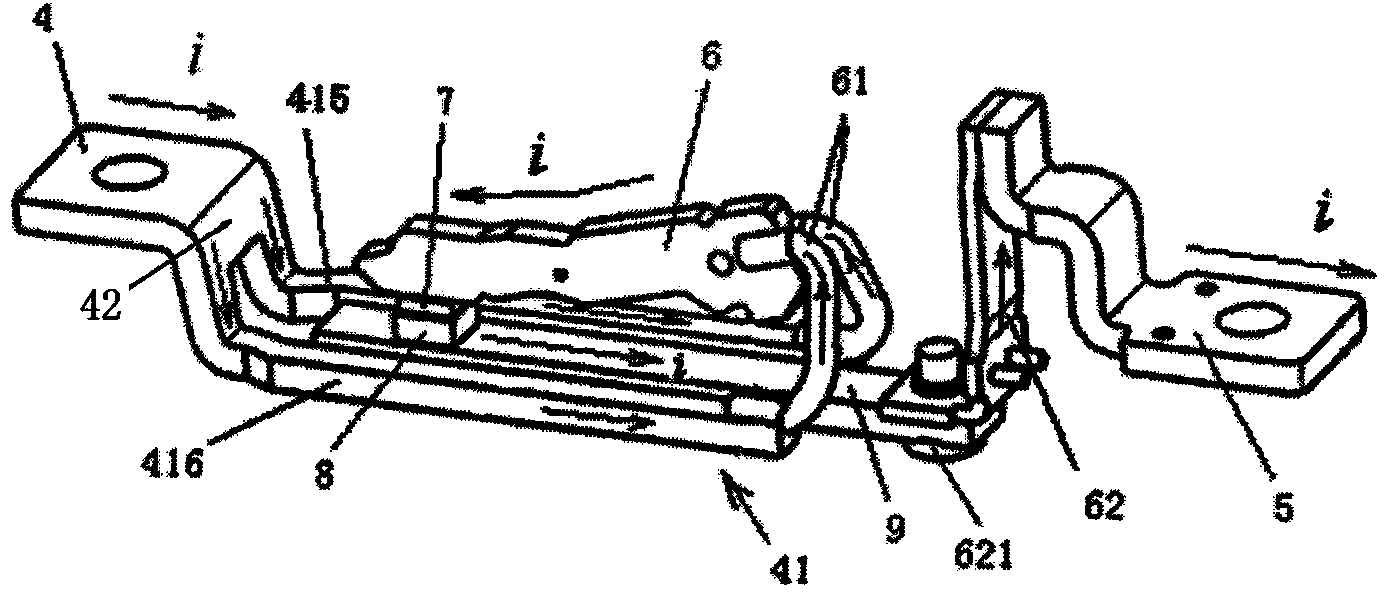
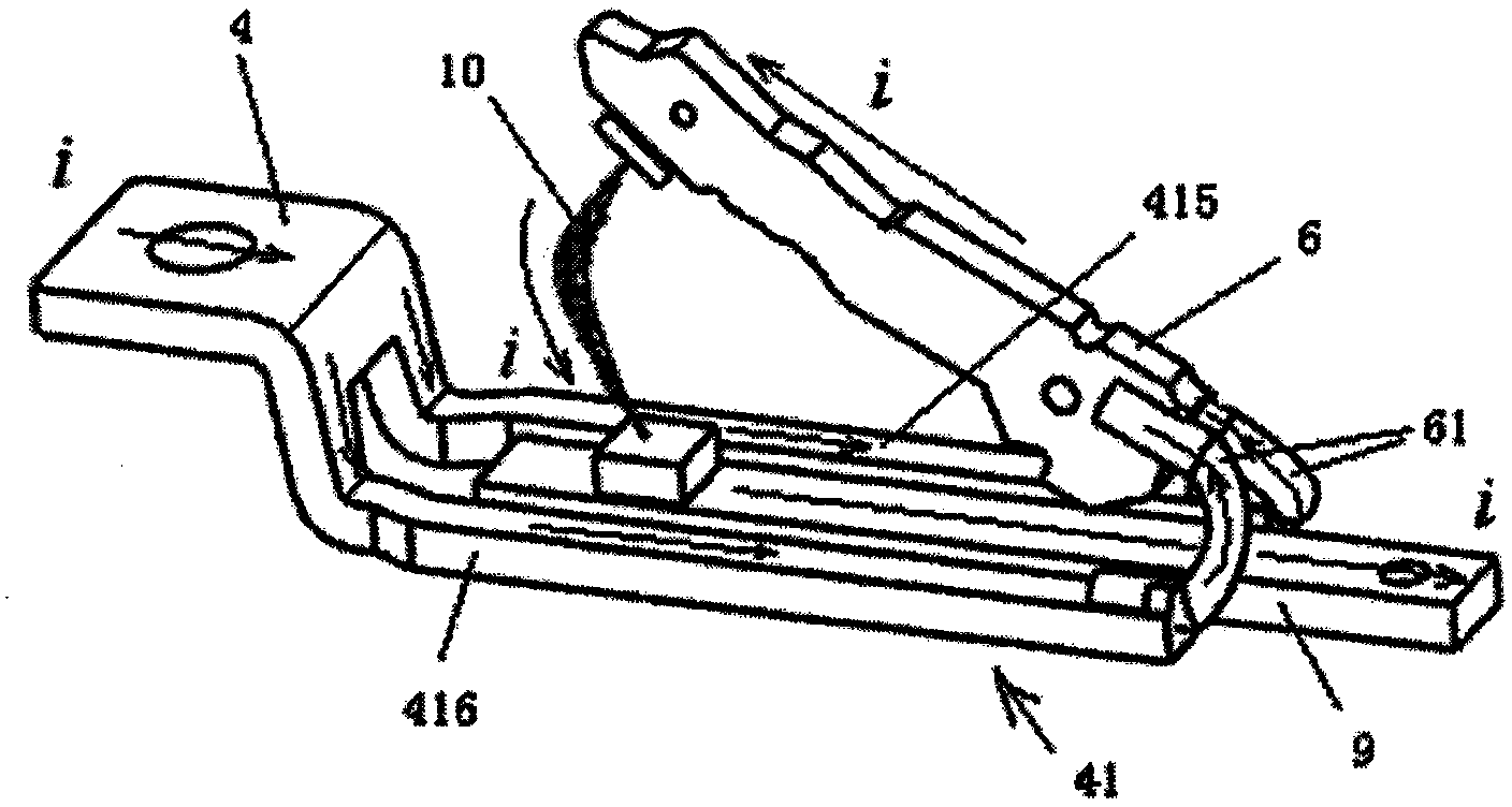
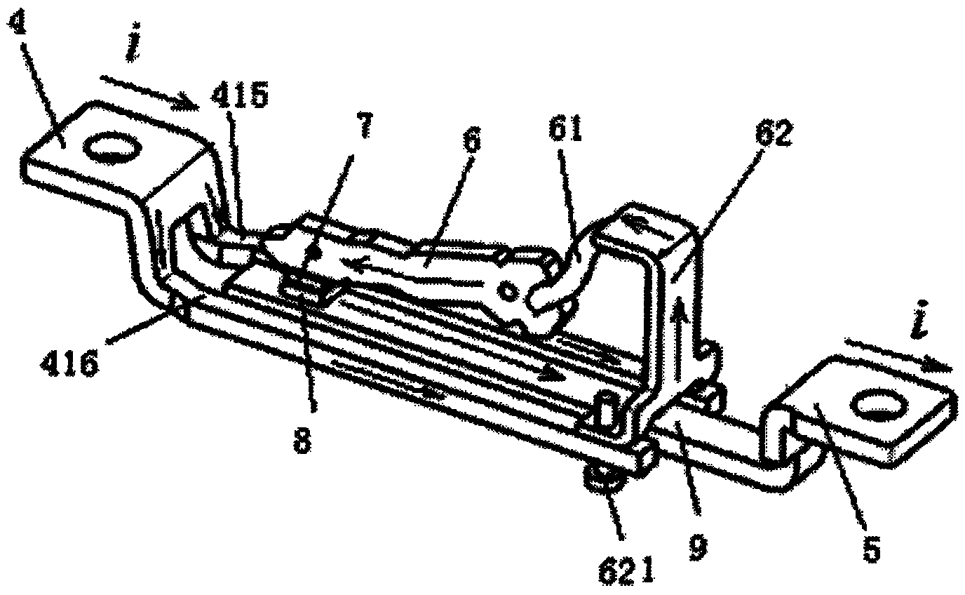
[0041] The conductive loop structure includes first and second connecting terminals 4 and 5, a movable guide rod 6, a movable contact 7 and a fixed contact 8, and the first connecting terminal 4 has a connecting guide rod extending toward one end of the second connecting terminal 5 41. Since the connecting guide rod 41 essentially act...

Embodiment 2

[0052] See image 3 , in this embodiment, the detection guide rod 62 of the conductive circuit is fixed to the end of the connecting guide rod 41 facing the second connection terminal 5 with a screw 621, more specifically to the first and second conductive arms 415, 416. One end facing the second connecting terminal 5 . One end of the aforementioned electrical connection device 61 , that is, a wire braided wire, is connected to the movable guide rod 6 , and the other end is connected to the detection guide rod 62 , so that the electrical connection device 61 appears as an indirect electrical connection with the connection guide rod 41 . And the second connection terminal 5 is directly fixedly connected with the fixed guide rod 9 , so that the end of the fixed guide rod 9 facing the second connection terminal 5 is directly electrically connected with the second connection terminal 5 . All the other are the same as the description to embodiment 1.

Embodiment 3

[0054] See Figure 4 , the figure shows that the electrical connection device 61 is a rigid connection conductor (because what embodiment 1 uses is a wire braided wire, so it can be called a flexible connection conductor), and the movable guide rod 6 is hinged on this connection through a pin shaft 63 On the rigid connection conductor, that is, the movable guide rod 6 is pivoted on the rigid connection conductor through the pin shaft 63, and elastic components (not shown) such as clip springs are used to give the rigid connection conductor and the connection guide Appropriate contact force is applied between the rods 41, and the rigid connecting conductor faces the connecting guide rod 41 after the conductive spacer 64 is added. Figure 4 One end of the second connection terminal 5 not shown in the figure is fixed, more specifically, it is fixedly connected with the end of the first and second conductive arms 415 , 416 facing the second connection terminal 5 . All the othe...


PUM


Abstract

A conductive loop structure of a switch device belongs to the technical field of a low-voltage electric appliance. The conductive loop structure comprises a first wiring terminal, a second wiring terminal, a movable guide rod, a stationary guide rod and a pair of movable contact and stationary contact, which can be separated and closed, wherein one end of the first wiring terminal extends to provide with a connecting guide rod, and the conductive loop structure is characterized in that the stationary guide rod is in noncontact parallel with the connecting guide rod, the end of the stationary guide rod below the movable rod, which is close to the second wiring terminal, is connected with the second wiring terminal, the movable guide rod is connected with the end of the connecting guide rod, which faces towards the second wiring terminal, under the state that a conducted electric loop is formed between the first wiring terminal and the second wiring terminal, and the current direction flowing by the connecting guide rod is identical to that flowing by the stationary guide rod and opposite to that flowing by the movable guide rod. The conductive loop structure has advantages that the breaking time of the fault current can be shortened, and the current limiting capacity of the switch device can be improved; and an arc extinguishing capacity of an arc extinguishing mechanism and the breaking capacity of the switch device can be improved.

Description

technical field [0001] The invention belongs to the technical field of low-voltage electrical appliances, and in particular relates to a conductive circuit structure of a switch device. Background technique [0002] The switchgear mentioned above refers to the low-voltage switchgear. The low-voltage switchgear is essentially a power distribution switch, which is usually used in low-voltage power distribution systems with AC 50Hz or 60Hz and rated In the low-voltage power distribution system with a voltage of 1500V and below, its function is to connect, carry and break the current under normal working conditions of the circuit, and it can also break the fault current under the specified abnormal working conditions of the circuit such as overload and short circuit. Protective effects. [0003] Figure 12 Shown is the conductive circuit structure diagram of the switchgear in the prior art. The switchgear includes an operating mechanism 1, an arc extinguishing mechanism 2 and a...

Claims


Application Information

Patent Timeline
Patent Type & Authority Patents(China)
IPC IPC(8): H01H71/10H01H71/08
Inventor 陈红影刘洪武管瑞良谢心意陆伟文
Owner CHANGSHU SWITCHGEAR MFG CO LTD (FORMER CHANGSHU SWITCHGEAR PLANT)
Why Eureka
Try Eureka