
High-efficiency and low-cost forward-flyback DC-DC (direct current-direct current) converter topology

A technology of DC-DC and converter, applied in the field of switching power supply

Inactive Publication Date: 2013-01-23
SANTAK ELECTRONICS SHENZHEN
View PDF5 Cites 32 Cited by
  • Summary
  • Abstract
  • Description
  • Claims
  • Application Information

AI Technical Summary

Problems solved by technology

[0006] The present invention was developed to solve the above mentioned problems

Method used


Image

  • High-efficiency and low-cost forward-flyback DC-DC (direct current-direct current) converter topology
  • High-efficiency and low-cost forward-flyback DC-DC (direct current-direct current) converter topology
  • High-efficiency and low-cost forward-flyback DC-DC (direct current-direct current) converter topology

Examples


Embodiment Construction

[0027] The following describes preferred embodiments according to the present invention with reference to the accompanying drawings. In the accompanying drawings, similar reference numerals represent similar elements, so they will not be described in detail again. "U" and "V" are symbols representing voltage , are used indiscriminately below.

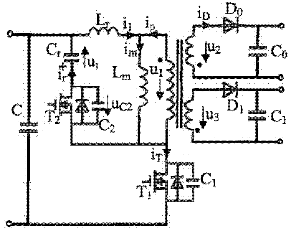
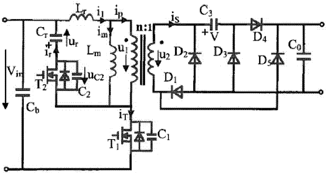
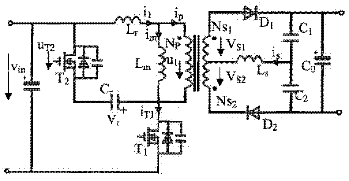
[0028] image 3 shows an equivalent circuit diagram of an active-clamp forward-flyback DC-DC converter topology according to an embodiment of the present invention, in image 3 Among them, Lr and Lm represent the leakage inductance and excitation inductance separated from the actual transformer equivalent model, respectively, and the transformer is an ideal transformer. Depend on image 3 It can be seen that the topology of the DC-DC converter according to this embodiment includes a high frequency transformer, a main switch T1, an active clamp circuit, rectifier diodes D1 and D2, a resonant circuit and an output capacitor C0.

[0029...


PUM


Abstract

The invention relates to a high-efficiency and low-cost forward-flyback DC-DC (direct current-direct current) converter topology. The forward-flyback DC-DC converter topology comprises a transformer, a main switch tube, a clamp circuit, a first rectification switch tube, a second rectification switch tube, an LC resonance circuit and an output capacitor, wherein a primary winding of the transformer is connected in series with the main switch tube between a first input end and a second input end; the clamp circuit consisting of a clamp capacitor and a clamp switch tube which are connected in series is connected in parallel with the primary winding or the main switch tube; a secondary winding of the transformer comprises a forward winding and a flyback winding; one end making the current flow into the primary winding is a dotted end of the primary winding; the secondary side of the transformer is connected in a manner that: the dotted end of the forward winding is connected to the first output terminal through the first rectification switch tube, and the dotted end of the flyback winding is connected to the second output terminal through the second rectification switch tube; the LC resonance circuit is connected to the first output terminal and the second output terminal and the unlike ends of the forward winding and the flyback winding so as to switch on or switch off the first rectification switch tube and the second rectification switch tube at zero current; and the output capacitor is connected between the first output terminal and the second output terminal.

Description

technical field [0001] The invention relates to the field of switching power supplies, in particular to a direct current-direct current (DC-DC) converter. Background technique [0002] DC-DC converters have been commercialized and widely used in UPS systems, battery charging and discharging devices, electric vehicles, starting / generating systems, aerospace power systems, remote and data communication systems, computer equipment, office automation equipment, industrial instruments instruments etc. According to different working modes, DC-DC converters can be divided into buck, boost, buck / boost, flyback, forward, half-bridge, full-bridge, push-pull and other topologies structure. With the improvement of performance requirements for switching power supplies, new circuit topologies need to be developed to realize high-efficiency DC-DC converters. [0003] Due to the advantages of low cost and wide input voltage range, the active clamp flyback DC- DC converter. The active c...

Claims


Application Information

Patent Timeline
IPC IPC(8): H02M3/337H02M1/00
CPCY02B70/1491H02M3/3353Y02B70/1433H02M3/33569H02M2001/0058H02M3/337Y02B70/10H02M1/0058H02M3/01H02M3/33507H02M3/33523H02M3/33538H02M3/33553
Inventor 胡智伦顾亦磊温志伟张昌丹
Owner SANTAK ELECTRONICS SHENZHEN
Learn More