
Eureka
For R&D, Eureka makes reading and utilizing patents & technical documents easy.
Eureka AIR
Designed for self-driven R&D workflows. Generate viable solutions, solve complex R&D challenges, empower your innovation with AI.

Eureka Materials
Designed for material experts only. Revolutionize your material R&D, from search, analyze, to developing new materials.

TechResearch
Generate reliable direction feasibility study reports for your R&D in just a few steps.

TechSeek
Discover and master advanced knowledge NOW. Basics, ideas, possibilities, all at once.

TechMind
As an expert in R&D Theories, TechMind can generates customized viable solutions instantly.

TechRisk
Analyze your overall solution with one click, know your potential R&D risks in advance.

TechMonitor
Get weekly tech updates, stay abreast of the latest tech innovations and key insights.
Device, system and method for monitoring looped network fault detecting, positioning and alarmings
A fault location, ring network fault technology, applied in transmission systems, digital transmission systems, data exchange networks, etc., can solve problems such as affecting work efficiency
- Summary
- Abstract
- Description
- Claims
- Application Information
AI Technical Summary
Problems solved by technology
Method used
Image

Examples
Embodiment 2
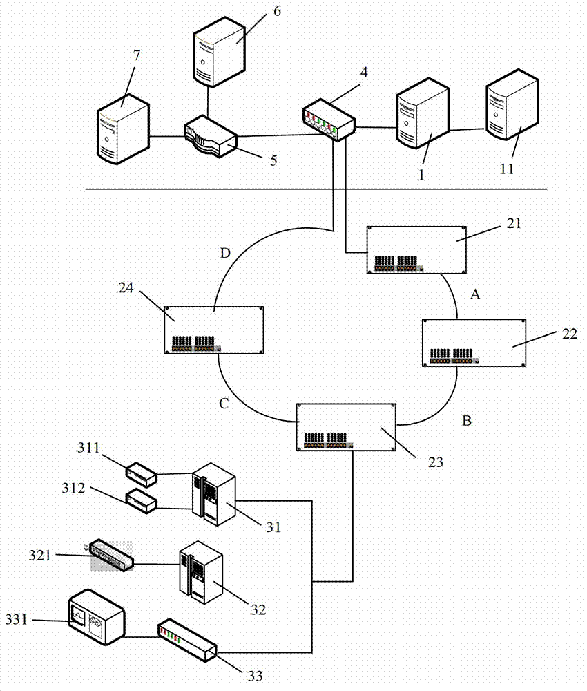
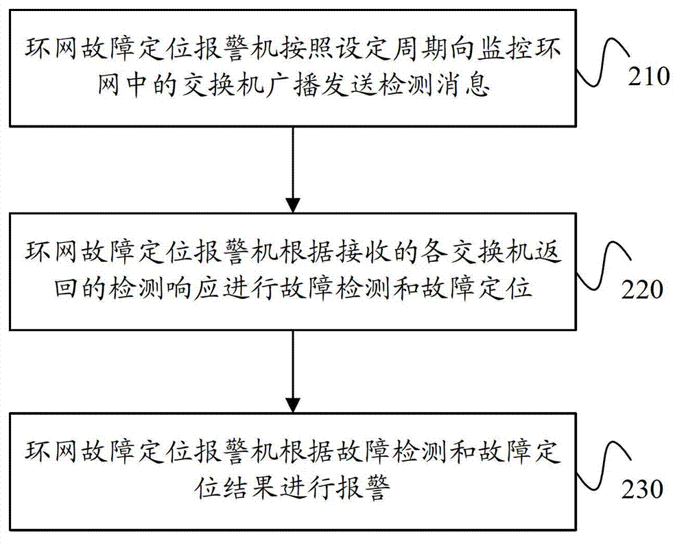
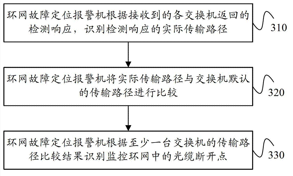
[0091] image 3 It is a flow chart of a method for detecting, locating and alarming a monitoring ring network fault provided by Embodiment 2 of the present invention. A type of fault that often occurs in the ring network is the disconnection of a single optical cable in the ring network, such as figure 1 As shown, the optical cables A, B, C, and D connecting each ring network switch may be disconnected. In this embodiment, the disconnection of the optical cable B connecting the second ring network switch 22 and the third ring network switch 23 is taken as an example to illustrate how the ring network positioning alarm device 7 detects and locates a single optical cable disconnection fault.
[0092] This embodiment can be based on the foregoing embodiments, and specifically optimize the operation of performing fault detection and fault location according to the received detection responses returned by each switch, which specifically includes the following steps:
[0093] Step...
Embodiment 3
[0101] Figure 4 It is a flow chart of a method for detecting, locating and alarming a monitoring ring network fault provided by Embodiment 3 of the present invention. The second type of failure that often occurs in the ring network is that the interface module of the ring network switch is abnormal. The interface module can be an RJ45 module. In this embodiment, the ring network switch is, for example, the AW3112 chip of Zhengwei Technology, which supports up to 6 substations, and each switch is equipped with 8 RJ45 modules, and each RJ45 module has an interface identifier. When a substation fails, the corresponding RJ45 module will be abnormal. Next, it will be specifically described how the ring network fault location alarm machine 6 detects and locates the fault.
[0102] Specifically, in the above embodiment, the operation of performing fault detection and fault location according to the received detection responses returned by each switch includes the following steps:...
Embodiment 4
[0109] Figure 5 It is a flow chart of a method for detecting, locating and alarming a monitoring ring network fault provided by Embodiment 4 of the present invention. When a single optical cable disconnection fault occurs in the ring network, if it cannot be detected and taken measures in time, a second breakpoint will occur, that is, a dual optical cable disconnection fault. When the two-way optical cable is disconnected in the monitoring ring network, it may cause large-scale gas data upload interruption, personnel positioning system data interruption, industrial control failure, etc., which will bury hidden dangers for safe production and may cause unpredictable Loss. Therefore, how to detect and locate the two-way fault is particularly important. In this embodiment, the disconnection of the optical cable B and the optical cable C is used as an example for illustration.
[0110] In this embodiment, the operation of performing fault detection and fault location according ...
PUM
 Abstract
Description
Claims
Application Information
 - R&D Engineer
- R&D Manager
- IP Professional
- Industry Leading Data Capabilities
- Powerful AI technology
- Patent DNA Extraction
Browse by: Latest US Patents, China's latest patents, Technical Efficacy Thesaurus, Application Domain, Technology Topic, Popular Technical Reports.
© 2024 PatSnap. All rights reserved.Legal|Privacy policy|Modern Slavery Act Transparency Statement|Sitemap|About US| Contact US: help@patsnap.com