Image pickup apparatus capable of changing operation condition of image sensing device and control method therefor

A technology of camera equipment and camera devices, which is applied to color TV parts, TV system parts, electrical components, etc., can solve the problems of increased dynamic range, narrowed dynamic range, and difficulty in reducing noise at the same time, achieving reduction Effects of Noise and Ensuring Dynamic Range

Active Publication Date: 2013-01-23
CANON KK
View PDF8 Cites 6 Cited by
  • Summary
  • Abstract
  • Description
  • Claims
  • Application Information

AI Technical Summary

Problems solved by technology

[0004] It should be noted that as the FD capacitance increases, not only the dynamic range increases but also the noise
On the other hand, as mentioned earlier, the dynamic range becomes narrower with a smaller FD capacitance
[0005] According to the imaging apparatus disclosed in Japanese Patent Laid-Open No. 2000-165754, the dynamic range can be expanded, however, it is difficult to reduce noise and expand the dynamic range at the same time
In the case of, for example, adding pixel data of the same column, it is difficult to achieve dynamic range expansion and noise reduction at the same time

Method used


Image

  • Image pickup apparatus capable of changing operation condition of image sensing device and control method therefor
  • Image pickup apparatus capable of changing operation condition of image sensing device and control method therefor
  • Image pickup apparatus capable of changing operation condition of image sensing device and control method therefor

Examples


no. 1 example

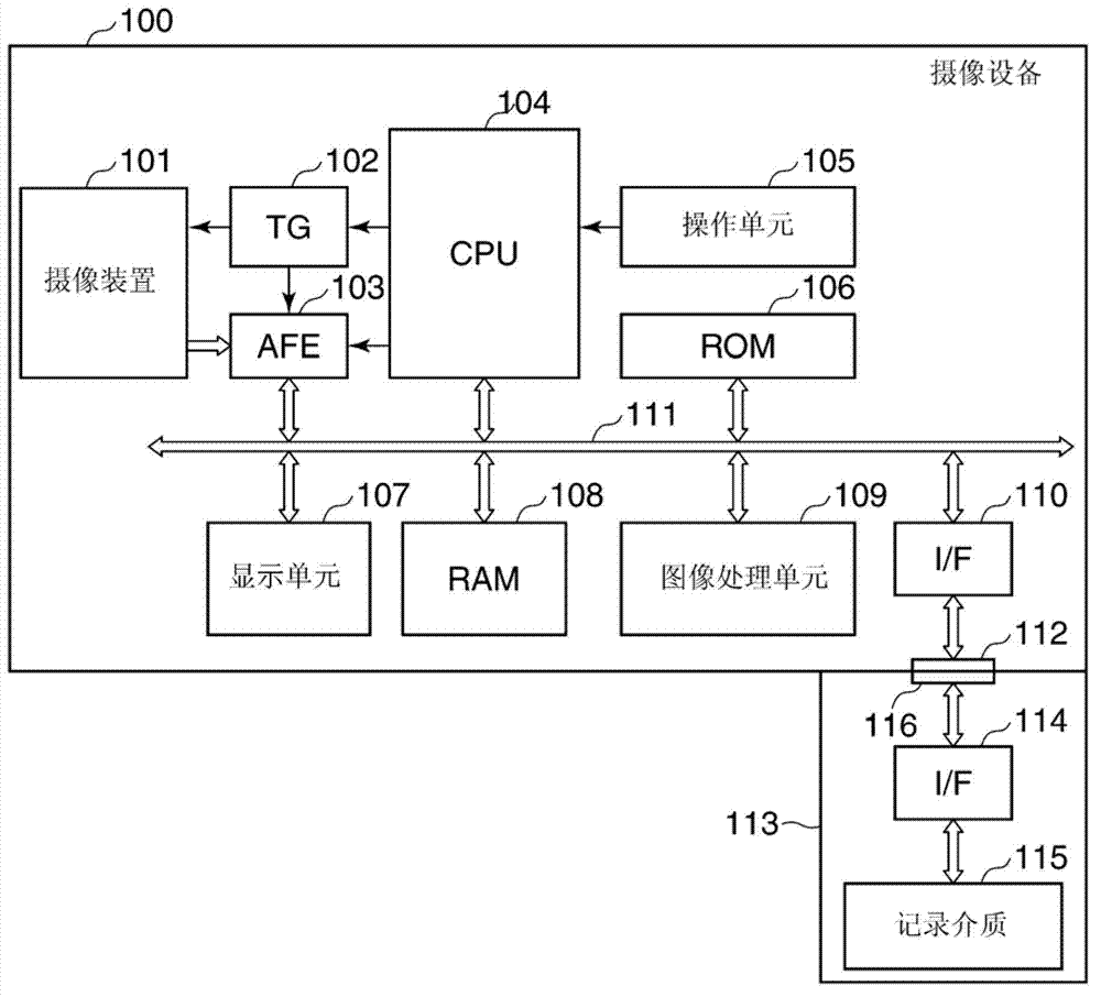
[0028] figure 1 An example of the imaging apparatus according to the first embodiment of the present invention is shown in a block diagram.

[0029] exist figure 1 Among them, the imaging apparatus 100 as a digital camera has, for example, a still image capturing function and a moving image capturing function. The imaging apparatus 100 includes a CPU 104 for controlling the imaging apparatus 100 as a whole, and includes an imaging device 101 formed with an optical image through an imaging lens (not shown). The imaging device 101 converts an optical image formed thereon into a series of electrical signals (analog pixel signals).

[0030] The analog pixel signal output from the imaging device 101 is gain-adjusted in an analog front end (hereinafter referred to as AFE) 103, and then converted into a digital signal (image data) with a predetermined number of quantization bits by the AFE 103 . Under the control of the CPU 104 , a timing generator (TG) 102 controls the operation ...

no. 2 example

[0154] Next, an example of an imaging apparatus according to a second embodiment of the present invention will be described. It should be noted that, except with Figure 2A and 2B Except for the column amplifiers (amplification units) corresponding to the column amplifiers 23a, 23b shown, the imaging apparatus of this embodiment is structurally similar to figure 1 The imaging apparatus 100 shown is the same.

[0155] Figure 10 The structure of each column amplifier of the imaging device 101 of this embodiment is shown.

[0156] Figure 10 The column amplifiers shown have variable gains that vary as described later. The column amplifier includes an input capacitor 303 that clamps pixel signals sequentially output from corresponding pixels of the imaging device 101 . The input capacitor 303 is connected to an inverting input terminal (−) of a differential amplifier 301 having a non-inverting input terminal (+) to which a reference voltage 302 is applied.

[0157] The colum...


PUM


Abstract

An image pickup apparatus capable of ensuring a dynamic range suitable for an image shooting condition and capable of reducing noise. The image pickup apparatus includes an image sensing device having floating diffusion units that are provided corresponding to pixels and that convert electrical charges accumulated in the pixels into voltage signals, which are output as pixel signals from pixel amplifiers. At that time, according to an image shooting condition, at least parts of connection switches corresponding to the floating diffusion units are sequentially turned on or all the connection switches are turned off, whereby the connection switches are connected to or disconnected from connection lines to thereby change capacity components connected to pixel amplifiers. This contributes to dynamic range expansion or noise reduction.

Description

technical field [0001] The present invention relates to an imaging apparatus such as a digital camera capable of changing operating conditions of an imaging device in accordance with image capturing conditions and a control method thereof. Background technique [0002] Some imaging apparatuses are configured to operate an imaging device such as a CMOS sensor or the like under operating conditions that vary according to image capturing conditions. For example, there is an imaging apparatus that increases the gain of a pixel amplifier of an imaging device as the image capturing sensitivity increases. For this reason, floating diffusion units (hereinafter each referred to as FD) for accumulating charges generated in the pixels are respectively configured to have small capacitances. However, as the FD capacitance decreases, the amount of charge that can be transferred decreases, and as a result, the so-called dynamic range narrows. [0003] In order to avoid this problem, ther...

Claims


Application Information

Patent Timeline
Patent Type & Authority Applications(China)
IPC IPC(8): H04N5/357H04N5/355H04N9/04
CPCH04N5/3745H04N5/357H04N5/361H04N5/378H04N9/04H04N5/355H04N5/347H04N25/46H04N25/57H04N25/63H04N25/77H04N25/75
Inventor 三本杉英昭
Owner CANON KK
Why Eureka
Try Eureka