Temperature distribution determining apparatus

A technology for determining temperature distribution and determining devices, applied to thermometers, temperature maps, measuring devices, etc., can solve problems such as determining three-dimensional space and time ultrasonic temperature distribution

Active Publication Date: 2013-01-23
KONINKLIJKE PHILIPS ELECTRONICS NV
View PDF6 Cites 19 Cited by
  • Summary
  • Abstract
  • Description
  • Claims
  • Application Information

AI Technical Summary

Problems solved by technology

The device can only measure the temperature distribution in the temperature range below 55°C, i.e. the device cannot determine the three-dimen

Method used


Image

  • Temperature distribution determining apparatus
  • Temperature distribution determining apparatus
  • Temperature distribution determining apparatus

Examples


Embodiment Construction

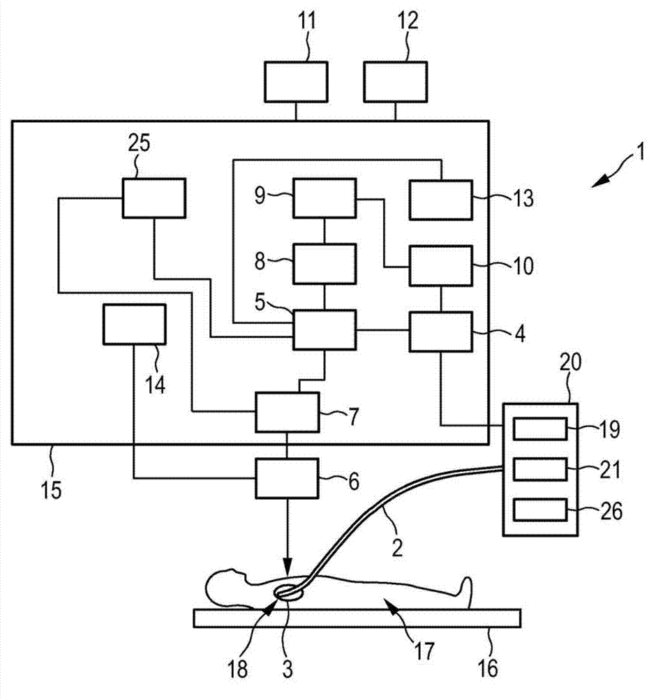
[0039] figure 1 A temperature distribution determining device 1 for determining a temperature distribution in an object 3 caused by applying energy to the object 3 is schematically shown as an example. In this embodiment, the object 3 is an organ of a human body 17 located on an examination table 16 . The organ 3 is, for example, the heart, the liver, one of the kidneys, etc. The area of ​​influence within object 3 has been predefined. For example, the physician has marked the affected area in the image of the subject 3 to pre-define the affected area. Predefined affected areas may mark lesions such as tumors within the object 3 . The images may be provided during previous measurements performed by imaging modalities such as magnetic resonance imaging systems, computed tomography imaging systems, nuclear imaging systems, ultrasound imaging systems, and the like.

[0040] The temperature distribution determining device 1 comprises a catheter 2 having a catheter tip 18 which...


PUM


Abstract

The invention relates to a temperature distribution determining apparatus for determining a temperature distribution within an object caused by applying energy to the object. A temperature distribution measuring unit (6, 7) measures a spatially and temporally dependent first temperature distribution in the object (3), while the energy is applied to the object (3) such that the object (3) is heated to a temperature within a first temperature range, and a temperature distribution estimating unit (5) estimates a spatially and temporally dependent second temperature distribution in the object (3) within a second temperature range, which is different to the first temperature range, based on the spatial and temporal dependence of the measured first temperature distribution. Since temperature distributions can be obtained not only in the first temperature range, but also in the second temperature range, the overall temperature range, in which the temperature distribution can be determined, can be increased.

Description

technical field [0001] The present invention relates to a temperature distribution determining device and method for determining a temperature distribution in an object caused by applying energy to the object. The invention also relates to a corresponding computer program for determining the temperature distribution within an object caused by the application of energy to the object. Background technique [0002] In the article "Three-dimensional spatial and temporal temperature imaging in gel phantoms using backscattered ultrasound" by Ajay Anand et al. (IEEE Transactions on Ultrasonics, Ferreoelectrics, and Frequency Control, Vol. 54, No. 1, pp. 23-31 (2007 Jan)) discloses a device for ultrasound-based temperature imaging. Ultrasound data is acquired from the gel phantom using backscattered ultrasound, and three-dimensional spatial and temporal ultrasound temperature distributions are determined from the acquired ultrasound data. The device can only measure the temperatur...

Claims


Application Information

Patent Timeline
IPC IPC(8): A61B18/00A61B18/12A61N7/00A61B17/00
CPCA61B2562/0204A61B2017/00084A61B18/00A61B8/463A61B2018/00803A61B8/485A61B8/483A61B8/5261A61B5/015A61B8/06A61B8/488A61B8/085A61N7/00A61B8/58A61B8/469A61B18/1206A61B8/48G01K11/24G01K2213/00G01K13/20
Inventor M·H·库恩
Owner KONINKLIJKE PHILIPS ELECTRONICS NV
Why Eureka
Try Eureka