Method for detecting insert objects in injection-moulded part

一种插入物、零件的技术,应用在涂层等方向,能够解决复杂评价系统等问题,达到省去启动、容易评估、节省高费用的分析的效果

Inactive Publication Date: 2013-01-23
KISTLER HLDG AG
View PDF8 Cites 9 Cited by
  • Summary
  • Abstract
  • Description
  • Claims
  • Application Information

AI Technical Summary

Problems solved by technology

However, it must be emphasized that the process has to be restarted after a machine interruption, which can lead to further complications, in particular through changed melting temperatures (to name just one example of this)
[0007] Furthermore, optical methods have proven to be problematic because they require complex evaluation systems since different gray-scale gradients must be evaluated reliably

Method used


Image

  • Method for detecting insert objects in injection-moulded part
  • Method for detecting insert objects in injection-moulded part

Examples


Embodiment Construction

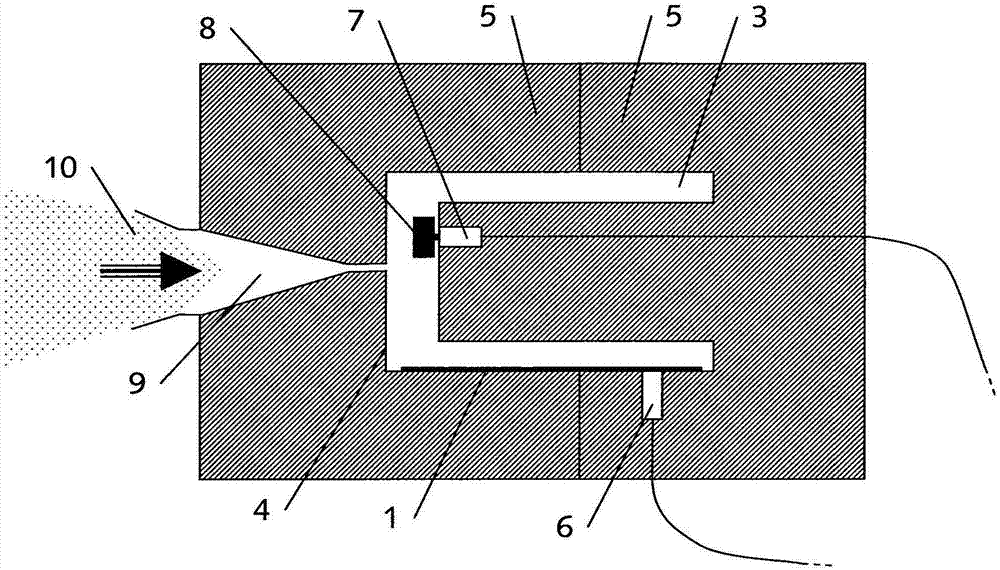
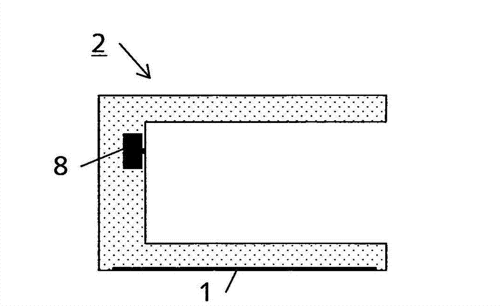
[0019] figure 1 A cross-sectional view of a mold 5 of an injection molding apparatus is shown. The mold 5 consists of two halves which together define a cavity 3 surrounded by mold walls 4 . In injection molding, an injection molded part 2 is formed in a cavity 3, such as figure 2 shown. For this purpose, a melt 10 of liquid plastic is injected into the cavity 3 through the spout 9 . After the melt 10 has solidified, the two mold halves 5 are opened and the finished injection molded part 2 is demoulded. An injection molding cycle ends here.

[0020] Inserts 1 , 8 can be inserted into cavity 3 before the two mold halves 5 are joined again to start a new cycle. When the melt 10 is injected, these inserts 1 are joined with the melt 10 to form an injection molded part 2 .

[0021] The method according to the invention for detecting inserts 1 , 8 in injection molded parts 2 will be described below.

[0022] According to the invention, at least one sensor 6 , 7 is installed ...


PUM


Abstract

The invention relates to a method for detecting an insert object (1, 8) in an injection-moulded part (2), the insert object (1, 8) being fixedly connected to the injection-moulded part (2) during the injection moulding by the insert object (1, 8) being placed in a cavity (3), which is surrounded by a mould wall (4) of a mould (5), before the beginning of the injection-moulding cycle. According to the invention, provided in the mould wall (4) is at least one temperature or pressure sensor (6, 7), which records and analyses at least one measured value at at least one point in time during an injection-moulding cycle. On the basis of the analysis it is established whether an insert object (1) was present at a specific location in the cavity (3) during the injection-moulding cycle. Finally, after it is ejected, the injection-moulded part (2) is sorted as an accepted part or a rejected part on the basis of the analysis of the measured value.

Description

technical field [0001] The invention relates to a method for detecting an insert in an injection molded (injection molded) part, wherein the insert is fixed to the injection molded part during injection molding by inserting the insert into a cavity before the injection molding cycle begins ground connection, wherein the cavity is surrounded by the mold walls of the mold. Background technique [0002] Inserts are often inserted into the cavity during injection molding in order to give the injection molded product a defined surface, for example by means of an outer foil. For example it could be a yogurt cup or an insulin syringe. The surface of such inserts has, for example, product-specific information, advertisements, expiration dates and / or barcodes. [0003] It can happen that deviations occur during the production of injection molded parts and that inserts are accidentally not inserted or too many inserts are inserted in the cavity. The injection molded parts produced ...

Claims


Application Information

Patent Timeline
Patent Type & Authority Applications(China)
IPC IPC(8): B29C45/84B29C45/77
CPCB29C2945/76638B29C2945/76535B29C2045/14918B29C2945/76739B29C45/842B29C2945/76859B29C45/77B29K2713/00B29K2711/08B29C2945/76501B29K2705/00B29C2945/76167B29C45/14065B29C45/14647B29C2945/76294B29C45/78
Inventor E·尼尔森
Owner KISTLER HLDG AG
Why Eureka
Try Eureka