

Vehicle control system, vehicle control method, and vehicle control program
A vehicle control system and vehicle control technology, applied in the field of vehicle control systems, can solve problems such as the inability to control vehicles smoothly
- Summary
- Abstract
- Description
- Claims
- Application Information
AI Technical Summary
Problems solved by technology
Method used
Image

Examples
no. 1 approach
[0043] [the whole frame]
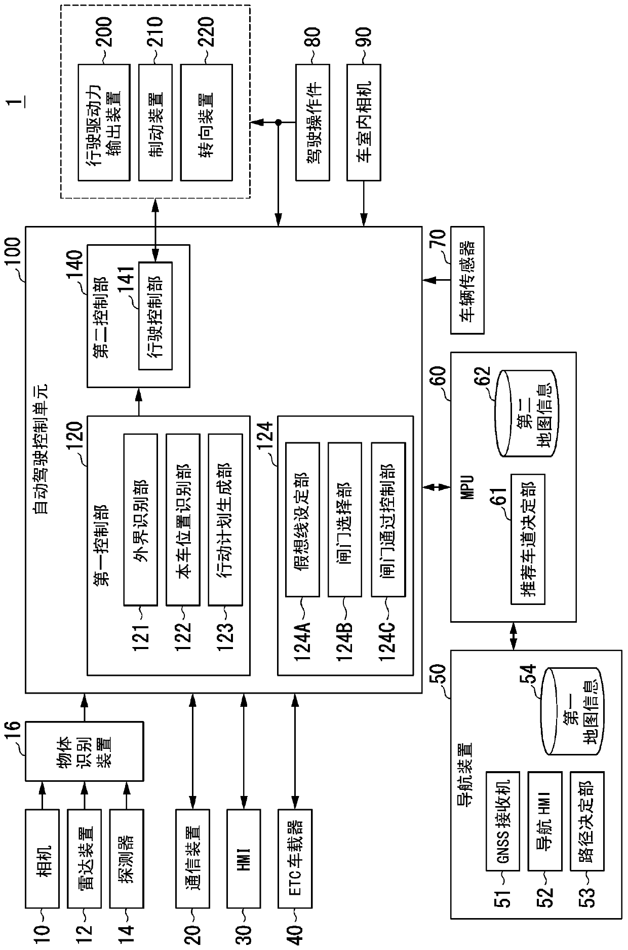
[0044] figure 1 It is a configuration diagram of the vehicle system 1 including the automatic driving control unit 100 . The vehicle on which the vehicle system 1 is mounted is, for example, a two-wheel, three-wheel, or four-wheel vehicle, and its drive source is an internal combustion engine such as a diesel engine or a gasoline engine, an electric motor, or a combination thereof. The electric motor operates using electric power generated by a generator connected to the internal combustion engine, or electric power discharged from a secondary battery or a fuel cell.
[0045] The vehicle system 1 includes, for example, a camera 10, a radar device 12, a detector 14, an object recognition device 16, a communication device 20, an HMI (Human Machine Interface) 30, an ETC (Electronic Toll Collection system) vehicle-mounted device 40, a navigation device 50, an MPU ( Micro-Processing Unit) 60 , vehicle sensor 70 , driving operation member 80 , interior c...
no. 2 approach
[0101] Hereinafter, a second embodiment will be described. In the first embodiment, no imaginary line is set in the imaginary line-free area AR2. On the other hand, in the second embodiment, a virtual line is also set in the virtual line-free area AR2. Hereinafter, the description will focus on differences from the first embodiment.
[0102] The imaginary line setting unit 124A sets an imaginary line corresponding to all gates and extending toward the road-demarcation-line-free area AR side.
[0103] Figure 8 It is a figure which shows another example of the situation in the vicinity of a gate. As shown in the drawing, the imaginary line setting unit 124A sets imaginary lines extending toward the front side from both ends of the respective column portions of the gates ( 1 ) to ( 6 ). This imaginary line is set, for example, in the area AR without road dividing lines.
[0104] At the end point of the set imaginary line and the end point of the main line, a plurality of im...
no. 3 approach
[0111] Hereinafter, a third embodiment will be described. In the third embodiment, the imaginary line setting unit 124A also sets an imaginary line in the no-road-dividing-line area AR based on the trajectories of other vehicles traveling in the no-road-dividing-line area AR in the past. Hereinafter, the description will focus on differences from the first embodiment.
[0112] Figure 9 It is a diagram showing an example of a traffic information providing system including a vehicle M equipped with the vehicle system 1 . The traffic information providing system includes an own vehicle M, one or more other vehicles m, and a traffic information management server 300 . The other vehicle m is equipped with, for example, a communication device that communicates with at least the traffic information management server 300 and a device that has a function of specifying the position of the vehicle. Another vehicle m equipped with these devices transmits the position information of th...
PUM
 Abstract
Description
Claims
Application Information