Electrostatic particle injector for RF particle accelerator

A particle accelerator and accelerator technology, applied in the field of resonators, can solve complex and expensive control problems

Inactive Publication Date: 2013-01-23
SIEMENS AG
View PDF5 Cites 2 Cited by
  • Summary
  • Abstract
  • Description
  • Claims
  • Application Information

AI Technical Summary

Problems solved by technology

Associated with this are complex and expensive control

Method used


Image

  • Electrostatic particle injector for RF particle accelerator

Examples


Embodiment Construction

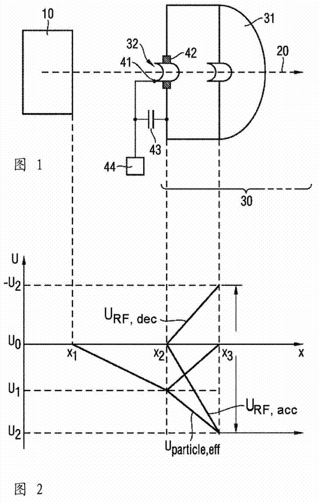
[0032] figure 1 An RF particle accelerator 1 is shown with an ion source 10 and a particle beam 20 exiting from the ion source 10 . in the direction of acceleration, that is, in figure 1 Arranged from left to right in the diagram behind the ion source 10 is an accelerator section 30 which usually has a plurality of cavity resonators. However figure 1 Only the first cavity resonator 31 of the accelerator section 30 is shown in section. The other cavity resonators are structurally indistinguishable from those of commercially available HF accelerators.

[0033] On the front side of the first cavity resonator 31 as viewed in the direction of the radiation, an electrode 41 is mounted which is designed as a ring electrode and surrounds the entrance opening 32 of the cavity resonator 31 . The ring electrode 41 is separated from the rest of the resonator structure of the first cavity resonator 31 by the insulator 42 , which is ideally also designed in the form of a ring. The “rem...


PUM


Abstract

The present invention relates to a method and a device for injecting charged particles into the first cavity resonator of an RF particle accelerator. An electrode is provided at the entrance to the first cavity resonator, which electrode is connected to a DC voltage source and generates a potential well that accelerates the particles leaving an ion source towards the first cavity resonator. As a result of the ion source and the accelerator path, i.e. more particularly the cavity resonators of the accelerator path, lying at a common potential, more particularly earth potential, the electrostatic potential well does not contribute to the overall energy of the particles, the overall acceleration effect is brought about by voltage induction in the RF resonator and the DC voltage source is not loaded by the beam current, and so the latter need not be precisely regulated or powerful.

Description

technical field [0001] The invention relates to a method and a device for injecting charged particles into a resonator of an HF particle accelerator. Background technique [0002] A typical HF particle accelerator essentially has an ion source and an accelerator section, which is formed from a plurality of cavity resonators. Charged particles leaving the ion source reach the first cavity resonator of the accelerator section and are accelerated there in a cascade into the individual resonators. A "first" cavity resonator refers to the first cavity resonator viewed in the direction of the beam or in the direction of acceleration. The necessary synchronization of the resonators of the accelerator section (or of the HF field present at the resonators) is achieved by a corresponding control which controls the HF high voltage source which is generated at the individual resonators HF voltage. Cavity resonators are also referred to as HF resonators. [0003] A major complication...

Claims


Application Information

Patent Timeline
Patent Type & Authority Applications(China)
IPC IPC(8): H05H7/22
CPCH05H7/08H05H7/22
Inventor O.海德
Owner SIEMENS AG
Why Eureka
Try Eureka