Device for stamping with adjustable distance between the rolls

A technology of stamping equipment and rollers, which is applied to cardboard articles, rotary printing machines, printing and other directions, can solve problems such as laborious processing, and achieve the effect of simple structure

Inactive Publication Date: 2013-01-30
GALLUS DRUCKMASCHINEN GMBH
View PDF14 Cites 5 Cited by
  • Summary
  • Abstract
  • Description
  • Claims
  • Application Information

AI Technical Summary

Problems solved by technology

A further disadvantage is that complex machined components, such as rolling pillows that can withstand high loads, must be used to guide the force flow

Method used


Image

  • Device for stamping with adjustable distance between the rolls
  • Device for stamping with adjustable distance between the rolls
  • Device for stamping with adjustable distance between the rolls

Examples


Embodiment Construction

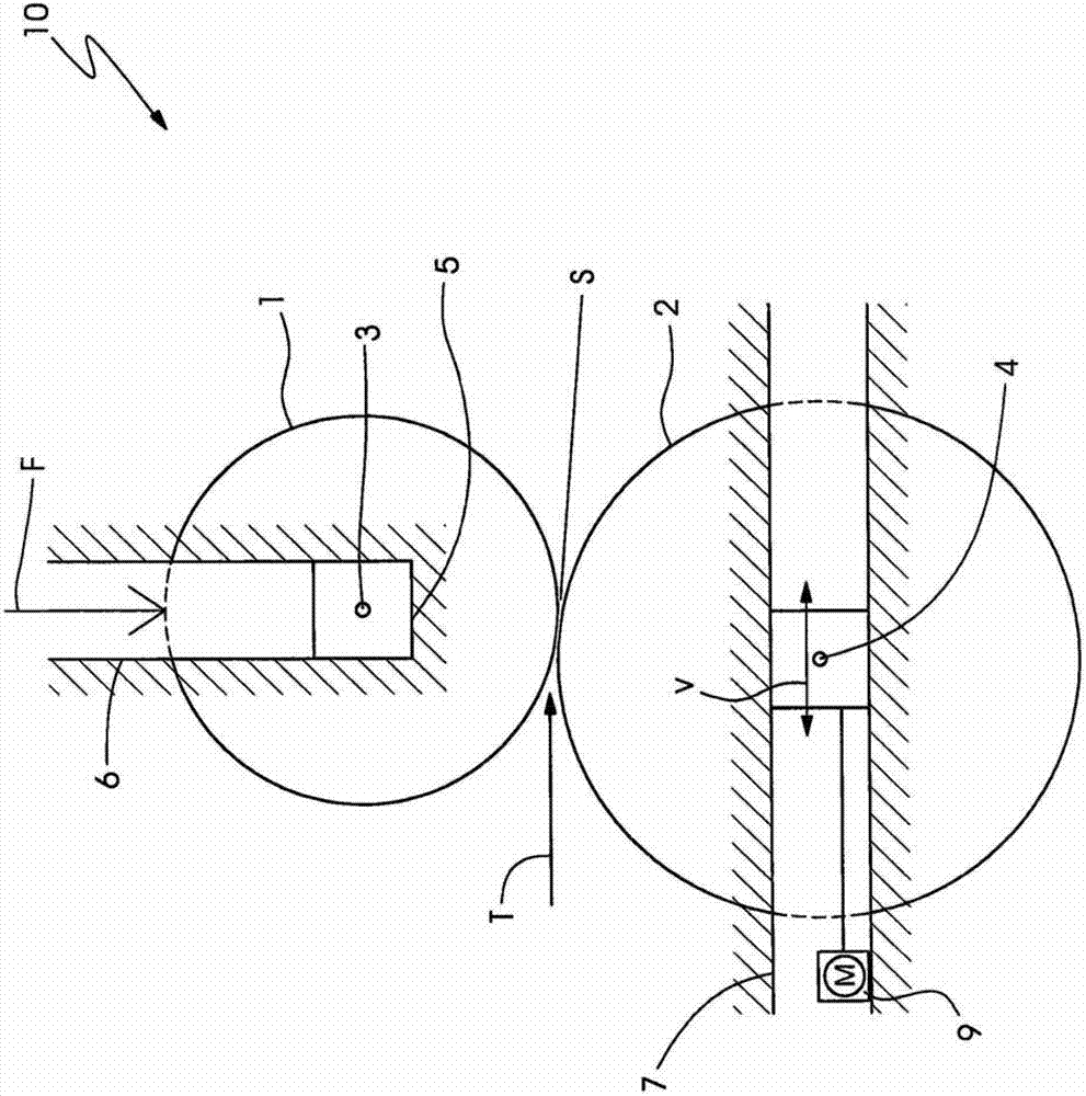
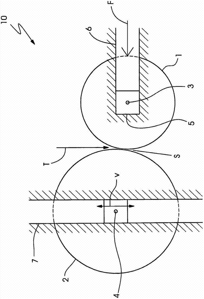
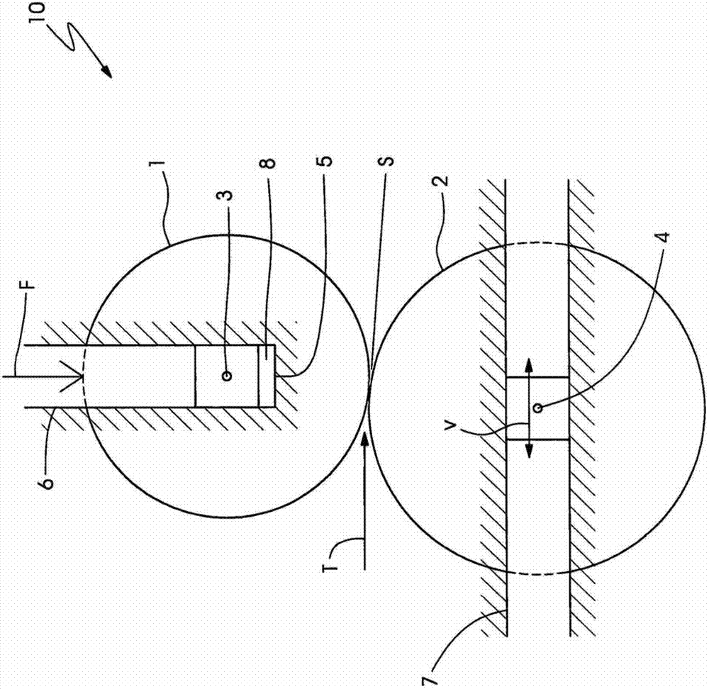
[0025] figure 1 A first embodiment of a punching device 10 according to the invention is shown with a punching cylinder 1 and a counter punching cylinder 2 which interact as tools and bring about the processing of a strip-shaped material 144 (not shown) conveyed in the conveying direction T . There is a gap S between the stamping cylinder 1 and the counterpressing cylinder 2 , that is to say, the stamping cylinder 1 and the counterpressing cylinder 2 are spaced apart from each other. In order to vary the effect of the stamping cylinder 1 on the sheet-shaped sheet 144 to be processed, the distance between the cylinders 1 , 2 , that is to say the gap S, can be varied. For this purpose, the counterpress cylinder 2 is mounted displaceably in a guide 7 , as indicated by the double arrow v. The counter punching cylinder 2 is thus displaceable in the horizontal direction along guides 7 . The movement can either be done manually or as figure 1 This is done by means of a drive 9 as...


PUM


Abstract

The punching apparatus (10) has a rotatable punching cylinder (1) about a rotational axis (3) and a rotatable cylindrical object (2) parallel to another rotational axis (4) of the punching cylinder, where a distance (S) between the punching cylinder and the cylindrical object is adjustable. The cylindrical object is slidably mounted in a guide (7). The clamping force (F) and the guide are aligned perpendicular to each other. In addition, the invention further relates to a narrow-width printer equipped with the device for stamping.

Description

technical field [0001] The invention relates to a punching machine as claimed in the preamble of claim 1 and to a narrow web printing machine as claimed in claim 10 . Background technique [0002] Apparatus for stamping flat multilayer objects with stamping rollers and counter-pressing rollers are known. At least one layer of the flat multilayer article can be punched through in the punching gap formed by the punching roller and the counter-pressing roller without all the layers being completely severed, wherein the width of the punching gap is adjustable . [0003] In this context, the term "stamping" is used in a narrow sense on the one hand, which means "cutting", "perforating" or "punching", and on the other hand it is also understood in a broad sense as "stamping", that is, " Deformation" or "press in". The same applies correspondingly for similar grammatical formations such as "stampable", which is understood in the narrow sense as "cuttable", "perforable" or "perfo...

Claims


Application Information

Patent Timeline
Patent Type & Authority Applications(China)
IPC IPC(8): B41F19/00
CPCB31D1/026B26D7/265B31D1/02B26D7/2628B26D7/2614B26F1/384B41F13/52B41F5/24B41F19/008B41F19/02B41P2219/00Y10T83/4812Y10T83/4833Y10T83/8745Y10T83/9312
Inventor T·德曼德
Owner GALLUS DRUCKMASCHINEN GMBH
Why Eureka
Try Eureka