Automatic brick clamping device

A brick clamping and automatic technology, applied in the field of brick loading and unloading equipment, can solve the problems of unstable brick clamps, inconvenient operation, high labor intensity, etc., and achieve the effects of simple structure, convenient operation and reduced labor intensity.

Active Publication Date: 2013-01-30
张金平
View PDF5 Cites 10 Cited by
  • Summary
  • Abstract
  • Description
  • Claims
  • Application Information

AI Technical Summary

Problems solved by technology

At present, the handling, loading, unloading and stacking of bricks are mainly carried out by manpower, which is labor-intensive and low-efficiency
There is also a kind of hanging brick fixture on the market, which carries b

Method used


Image

  • Automatic brick clamping device
  • Automatic brick clamping device
  • Automatic brick clamping device

Examples


Embodiment 1

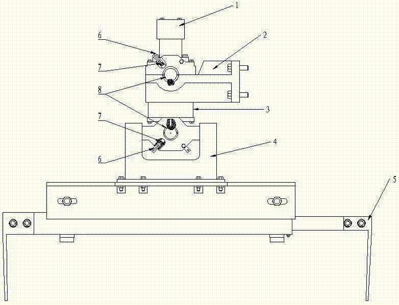
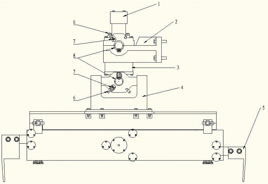
[0021] Such as figure 1 , Figure 6 As shown, an automatic brick clamping device includes a support frame 2 that can be connected with a movable mechanical arm, a hydraulic rotary joint 3, a hydraulic motor 1, a buffer balance seat 4, a brick clamping mechanism 5 and a hydraulic control mechanism. The hydraulic rotary joint 3 is suspended on the support frame 2, the hydraulic motor 1 is fixed on the end cover of the hydraulic rotary joint 3, the hydraulic motor 1 drives the spool 32 of the hydraulic rotary joint to rotate, and a valve core 32 is provided at the lower end of the hydraulic rotary joint Through hole 34, a transverse shaft passes through through hole 34 and is fixed on spool 32, and a set of buffer balance seat 4 and brick clamping mechanism 5 are installed respectively at the two ends of transverse shaft. In order to limit the shaking of the brick clamping device, supporting shafts 33 are provided on both sides of the housing 31 of the hydraulic rotary joint 3, ...

Embodiment 2

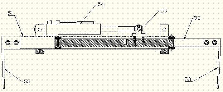
[0025] Embodiment 2 is different from Embodiment 1 in the brick clamping mechanism. Such as Figure 4 As shown, the brick clamping mechanism 5 in this embodiment is composed of a jacket 51, a clamp arm 52, a clamping plate 53, a hydraulic cylinder 54 and a gear transmission mechanism. A clamping arm 52 and two clamping plates are respectively provided at both ends of the jacket 51. 53 are respectively fixed on the top ends of the two clamp arms 52. Such as Figure 5 As shown, a gear 57 is provided between the two clip arms 52 , and a rack 56 meshing with the gear 57 is provided on the two clip arms 52 . The hydraulic cylinder 54 is fixed on the upper part of the jacket 51, and the hydraulic cylinder 54 drives one of the clamp arms to move through the pull rod 55, and drives the other clamp arm to move in the opposite direction through the gear 57 at the same time.

[0026] In addition, rolling shafts 58 are installed at both ends and in the middle of the jacket 51, so that ...


PUM


Abstract

The invention discloses an automatic brick clamping device comprising a support frame, a hydraulic rotation joint, a hydraulic motor, a buffer balance seat, a brick clamping mechanism and a hydraulic control mechanism, wherein the hydraulic rotation joint is suspended on the support frame, the hydraulic motor is fixed on an end cover of the hydraulic rotation joint and drives a valve plug of the hydraulic rotation joint to rotate, a through hole is formed in the lower end of the valve plug of the hydraulic rotation joint, a cross shaft passes through the through hole to be fixed on the valve plug, the buffer balance seat and the brick clamping mechanism are respectively installed on the two ends of the cross shaft, the buffer balance seat comprises a buffer block, a buffer seat, a spring and a balance seat, wherein the center of the buffer block is fixed on the cross shaft, the buffer block is installed in the buffer seat and is supported by the spring in the buffer seat, the balance seat is fixed below the buffer seat, and the brick clamping mechanism is installed on the balance seat. According to the automatic brick clamping device, the structure is simple, the operation is convenient, the clamping is stable, the work efficiency is high, the production efficiency is improved greatly, and the labor intensity is lowered.

Description

technical field [0001] The invention relates to a brick loading and unloading device, in particular to an automatic brick clamping device. Background technique [0002] Brick is a major building material. After the bricks are fired, the finished bricks need to be transferred from the kiln car to the carrier truck to be transported to the construction site. At present, the handling, loading, unloading and stacking of bricks are mainly performed by manpower, which is labor-intensive and low in efficiency. There is also a kind of hanging brick fixture on the market, which carries bricks by installing brick clamps on the door frame or suspenders, but there are still shortcomings, such as brick clamps are unstable and easy to shake, inconvenient to operate, difficult to control, and work Low efficiency and other issues. Contents of the invention [0003] The present invention aims at the problems existing in the above-mentioned prior art, and provides an automatic brick clamp...

Claims


Application Information

Patent Timeline
IPC IPC(8): B65G47/90
Inventor 张金平
Owner 张金平
Why Eureka
Try Eureka