Multipoint contact stepless variable transmission

A continuously variable transmission and multi-point contact technology, which is applied to friction transmission devices, elements with teeth, belts/chains/gears, etc., can solve problems such as difficult repairs, large space occupied by butterfly discs, and extremely high pressure control accuracy. , to achieve the effect of low requirements for manufacturing and maintenance environment, simple speed control method, and expanding the range of kinetic energy transmission

Active Publication Date: 2013-01-30
崔振华
View PDF9 Cites 8 Cited by
  • Summary
  • Abstract
  • Description
  • Claims
  • Application Information

AI Technical Summary

Problems solved by technology

[0004] (1) The steel belt type continuously variable transmission is hydraulically controlled, the pressure control accuracy is extremely high, the manufacturing cost is high, the parts are difficult to process, the parts pass rate is low, the failure rate is high, and the repair is difficult
[0005] (2) Steel ring CVT with two straight cone discs, single-point friction transmission power, low pass rate due to deformation of the steel ring, easy slipping during work, affecting transmission efficiency, and low reliability
[0006] (3) CVT with two cone discs and butterfly discs. Since the discs take up a lot of space, only two discs can be arranged at most, which is easy to slip, has extremely high machining accuracy, is large in size and costly, and there is no market for the product
[0007] The above-mentioned three kinds of continuously variable transmissions are friction transmission, single-point force transmission, low transmission efficiency, high manufacturing cost, low mechanical efficiency, complicated structure and control, high manufacturing and processing cost, high failure rate, and difficult maintenance

Method used


Image

  • Multipoint contact stepless variable transmission

Examples


Embodiment Construction

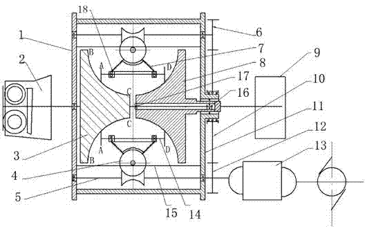
[0024] The present invention will be further described below in conjunction with accompanying drawing.

[0025] Such as figure 1 As shown, the multi-point contact continuously variable transmission of the present invention includes a transmission housing 1, an external power input part 2, an output end part 9, and the external power input part 2 and the output end part 9 are arranged outside the transmission housing 1, and the external power input Part 2 is connected with the active arc cone 3, the output part 9 is connected with the driven arc cone 8, the active arc cone 3 and the driven arc cone 8 are assembled into a cone assembly, and the active arc Cone disc 3 shafts are inserted into the driven arc cone disc 8. The inner hole of the driven arc disc 8 is fixed at the position of deep groove bearing 16 by the internal spline hole pressure plate to prevent axial movement. The inner hole of the small head Needle bearings 17 are adopted to make the two wheels rotate relative...


PUM


Abstract

The invention discloses a multipoint contact stepless variable transmission, which comprises a transmission shell (1), an outer power input part (2) and an output end part (9), wherein the outer power input part (2) is connected with a driving part (3); the output end part (9) is connected with a driven part (8); a plurality of variable speed control execution mechanisms are uniformly arranged on the peripheries of the driving part (3) and the driven part (8); the driving part (3) is a driving cambered cone plate; and the driven part (8) is a driven cambered cone plate. According to the multipoint contact stepless variable transmission, ten, eight, six or four barbell type ferry wheels can be uniformly distributed in the circumferential directions of the cambered cone plates according to the power of an engine, and a plurality of points independently work respectively, so that influence on the whole transmission function is avoided when a certain point instantly fails; and the mutual hot backup of the points is the application of a redundancy design concept to the transmission.

Description

technical field [0001] The invention relates to a continuously variable transmission, in particular to a multi-point contact continuously variable transmission. Background technique [0002] The speed change device can solve the effective matching of kinetic energy and potential energy, and is also a bridge between input and output. To maximize the efficiency of external input energy, the purpose of applying transmission in the automotive field is to make the engine work in the most fuel-efficient zone and adapt the vehicle to various road conditions. The friction drive continuously variable transmission works smoothly without impact, reduces the copper loss and iron loss of the mechanical system, prolongs the life of the machine, and has a good energy-saving effect. [0003] There are many disadvantages in the existing three types of CVT technologies; [0004] (1) Steel-belt continuously variable transmission is hydraulically controlled, requiring extremely high pressure ...

Claims


Application Information

Patent Timeline
IPC IPC(8): F16H15/06F16H37/02F16H61/32
Inventor 崔博琳
Owner 崔振华
Why Eureka
Try Eureka