Display driving method and display device applying same

A display driver and display device technology, applied to static indicators, instruments, etc., can solve problems such as failure to meet product power saving requirements, high power consumption, and shortened lifespan, and achieve the effect of reducing power

Active Publication Date: 2013-01-30
INNOCOM TECH SHENZHEN +1
View PDF2 Cites 1 Cited by
  • Summary
  • Abstract
  • Description
  • Claims
  • Application Information

AI Technical Summary

Problems solved by technology

[0004] However, in the traditional poly-Si (polycrystalline silicon) TFT (Thin Film Transistor, Thin Film Transistor) element characteristics (the gate drive circuit is formed on the external hard printed circuit board) and the a-Si (amorphous silicon) of GOP In terms of the characteristics of TFT components, in terms of mobility, the mobility of a-Si TFT is very different from that of poly-Si TFT
Therefore, to achieve the same driving capability, the size of a-Si TFT is larger than that of poly-Si TFT, resulting in increased power consumption of a-Si TFT
Moreover, if the power consumption increases, the electronic components / electronic products have overheating, shortened life, and cannot meet the power saving requirements of the product
[0005] Therefore, this case proposes a display driving method and a display panel using it, which can solve the problem of high power consumption encountered by existing ASG / GOP

Method used


Image

  • Display driving method and display device applying same
  • Display driving method and display device applying same
  • Display driving method and display device applying same

Examples


Embodiment Construction

[0018] In order to have a better understanding of the above and other aspects of the present case, the following specific examples are given in detail with reference to the attached drawings.

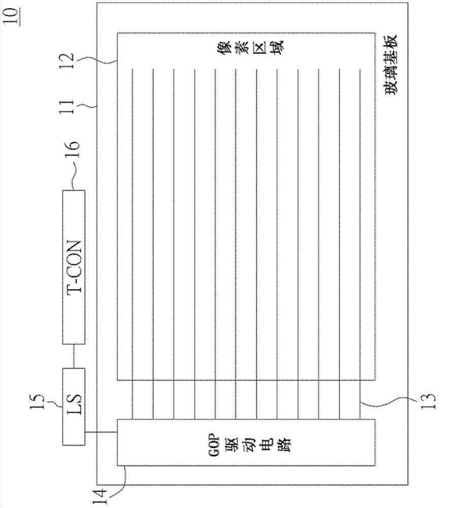
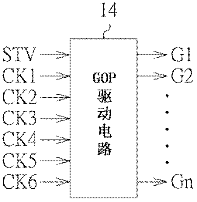
[0019] Please refer to figure 1 , which shows a schematic diagram of a display panel using the GOP technology. The display panel 10 includes a substrate 11 , a plurality of scan lines 13 , a GOP driving circuit 14 , a level shifting circuit (LS, Level Shifter) 15 and a timing controller (T-CON, Timing Controller) 16 . The substrate 11 is, for example, a glass substrate, which has a pixel area (active area) 12 , and the scan lines 13 are disposed in the pixel area 12 . The GOP driving circuit 14 is disposed on one side of the substrate 11 . The GOP driving circuit 14 is electrically connected to the scan lines 13 to drive the scan lines 13 . The timing controller 16 outputs various control signals and various clock signals, and these control signals and these clock signals are boosted...


PUM


Abstract

The invention discloses a display driving method applied to a display panel. The display driving method comprises the following steps of: generating an initial signal and at least one clock signal, wherein the clock signal comprises a first clock level, a second clock level and a third clock level at least which are mutually different in levels; generating at least one scanning signal according to the initial signal and / or the clock signal, wherein the scanning signal comprises a first scanning level, a second scanning level and a third scanning level which are mutually different in levels; and driving the display panel by virtue of the scanning signal. According to the display driving method of the embodiment of the invention and the display panel applying the display driving method, a multi-level scanning driving voltage is input to a scanning driving circuit (GOP, gate on panel) arranged on a panel, and power can be reduced.

Description

technical field [0001] The invention relates to a display driving method and a display panel using the same. Background technique [0002] The liquid crystal display panel has the advantages of light weight, long lifespan and high image quality, so that the liquid crystal display panel is widely used in various electronic devices. Such as mobile phones, TVs, computer screens, etc. Traditionally, gate drive circuitry is formed on an external rigid printed circuit board. [0003] In order to simplify the complexity and volume of the external gate drive integrated circuit, reduce the panel production cost and reduce the panel production time, an amorphous silicon gate (ASG, Amorphous Silicon Gate) or gate panel (GOP, Gate on Panel) has been developed. In the technology of thin film transistor arrays, the gate drive circuit for driving the scanning lines is formed on the substrate of the liquid crystal display panel. In this way, the complexity and size of the external gate d...

Claims


Application Information

Patent Timeline
Patent Type & Authority Applications(China)
IPC IPC(8): G09G3/20
Inventor 许文财江建学
Owner INNOCOM TECH SHENZHEN
Why Eureka
Try Eureka