Radial logarithmic spiral micro-stripe slow wave line

A logarithmic spiral and slow wave line technology, applied in the field of microwave vacuum electronic devices, can solve the problems that the DC input power of the traveling wave tube cannot be too large, the output power is limited, and the working voltage can be increased.

Inactive Publication Date: 2013-01-30
UNIV OF ELECTRONICS SCI & TECH OF CHINA
View PDF3 Cites 9 Cited by
  • Summary
  • Abstract
  • Description
  • Claims
  • Application Information

AI Technical Summary

Problems solved by technology

However, such a low voltage means that the DC input power of the TWT cannot be too large, and the corresponding output power is also limited, within a hundred watts
To increase its output power, it is necessary to increase the operating voltage. According to the traditional method, the cost is an exponential increase in the radial size of the structure, which is unacceptable.

Method used


Image

  • Radial logarithmic spiral micro-stripe slow wave line
  • Radial logarithmic spiral micro-stripe slow wave line
  • Radial logarithmic spiral micro-stripe slow wave line

Examples


Embodiment Construction

[0021] Specific embodiments of the present invention will be described below in conjunction with the accompanying drawings, so that those skilled in the art can better understand the present invention. It should be noted that in the following description, when detailed descriptions of known functions and designs may dilute the main content of the present invention, these descriptions will be omitted here.

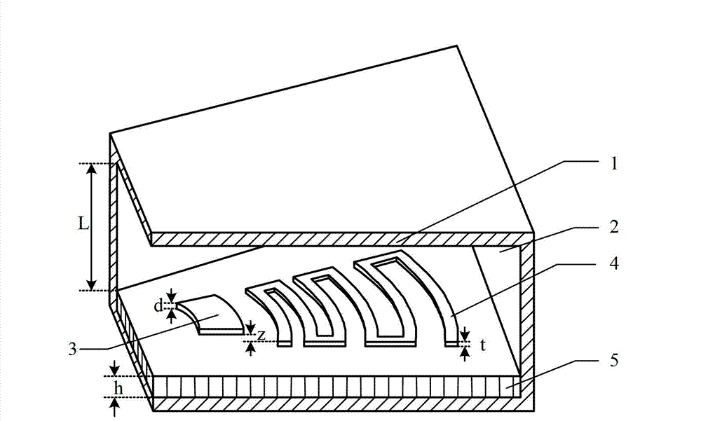
[0022] figure 1 It is a structural schematic diagram of a specific embodiment of the radial logarithmic spiral microstrip slow wave line of the present invention.

[0023] In this example, if figure 1 As shown, the radial logarithmic spiral microstrip slow wave line of the present invention is a quasi-periodic structure along the radial direction, and uses a plane fan-shaped electron beam to work. It can be regarded as composed of four parts, from top to bottom: fan-shaped vacuum chamber 2, angular radial logarithmic spiral metal belt 4, fan-shaped dielectric plate 5 and ...


PUM


Abstract

The invention discloses a radial logarithmic spiral micro-stripe slow wave line. The radial logarithmic spiral micro-stripe slow wave line is of a quasi-periodicity structure in the radial direction, operates by adopting a plane fan-shaped electron beam, and comprises a fan-shaped metal shielding shell, a fan-shaped medium base plate and an angle radial logarithmic spiral metal stripe; the angle radial logarithmic spiral metal stripe is a part of arc with an angle theta and metal stripes, wherein the part of arc is cut off from a single radial logarithmic spiral micro-stripe line and the metal stripes are adjacent to the part of arc and are connected end to end. A traveling wave tube with the radial logarithmic spiral micro-stripe slow wave line provided by the invention has working voltage far lower than that of the conventional low-voltage spiral line traveling wave tube and has great advantages relative to a coupled-cavity-type traveling wave tube; and compared with the radial logarithmic spiral micro-stripe slow wave line, the angle radial logarithmic spiral slow wave line has a wider working voltage tuning range, which means a wider direct-current input power tuning range and higher output power under the condition of equal electron beam current, so the angle radial logarithmic spiral slow wave line can be applied to the condition needing higher power.

Description

technical field [0001] The invention belongs to the technical field of microwave vacuum electronic devices, and more specifically relates to a radial logarithmic spiral microstrip slow wave line in a traveling wave tube. Background technique [0002] As the most widely used electric vacuum device in the microwave frequency band, the traveling wave tube has a prominent application status in many fields such as millimeter wave radar, guidance, communication, microwave remote sensing, and radiation measurement. Due to its irreplaceable broadband characteristics, it has also become the most important microwave tube in various fields of equipment. [0003] A typical traveling wave tube consists of five parts: electron gun, focusing system, slow wave line (slow wave structure), input and output devices and collector. As the core component of the traveling wave tube, the task of the slow wave line is to transmit the high-frequency electromagnetic traveling wave and reduce the phas...

Claims


Application Information

Patent Timeline
Patent Type & Authority Applications(China)
IPC IPC(8): H01J23/26
Inventor 王少萌宫玉彬侯艳魏彦玉段兆云
Owner UNIV OF ELECTRONICS SCI & TECH OF CHINA
Why Eureka
Try Eureka