
Method for designing array antenna with circular aperture field distribution based on Sinc function

An array antenna and design method technology, applied in the direction of antenna, antenna array, electrical components, etc., can solve the problems that a single antenna cannot meet the far-field lobe pattern control, cannot meet the gain requirements, and lacks beamforming control, etc. Achieve the effects of avoiding random optimization algorithms, convenient design, and fast beamforming

Inactive Publication Date: 2013-01-30
ZHEJIANG UNIV
View PDF3 Cites 19 Cited by
  • Summary
  • Abstract
  • Description
  • Claims
  • Application Information

AI Technical Summary

Problems solved by technology

[0002] With the rapid development of wireless communication, a single antenna can no longer satisfy the control of the far-field lobe pattern. A single microstrip, helical antenna, and horn antenna cannot meet the gain requirements
[0003] In recent years, antenna array technology has been widely used in radar, satellite communication and other systems. However, in order to obtain the position and excitation of array elements in the design of array antennas, some global optimization algorithms (genetic algorithm, particle swarm algorithm, differential Evolutionary algorithm, etc.), the time spent increases exponentially with the increase of array elements, and the final result may not be the optimal result, and the implementation efficiency for a slightly larger array is very low

Method used


Image

  • Method for designing array antenna with circular aperture field distribution based on Sinc function
  • Method for designing array antenna with circular aperture field distribution based on Sinc function
  • Method for designing array antenna with circular aperture field distribution based on Sinc function

Examples


Embodiment

[0035] Such as Figure 4 As shown, a concentric circle array layout structure composed of three concentric rings is adopted. There are 4 antenna units A1 on the innermost concentric ring, 8 antenna units A2 on the middle concentric ring, 16 antenna units A3 on the outermost concentric ring, R 1 , R 2 , R 3 are the radii of the innermost circle, the middle circle, and the outermost circle of concentric rings, respectively.

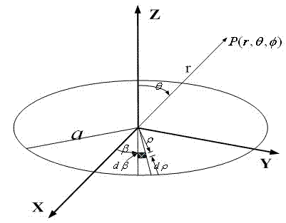
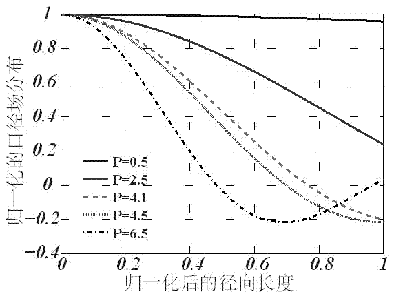
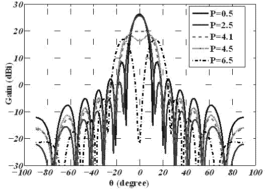
[0036] Such as figure 2 As shown, where P is the internal weighting parameter, the abscissa is the radial coordinate of the normalized radius a, and the y-coordinate is the magnitude of the aperture field, the internal weighting parameter P is 0.5, 2.5, 4.1, 4.5, 6.5, respectively Transform Weighted Quasi-Sinc Function The aperture field distribution of figure 2 As shown, the aperture field distribution is rotationally symmetric about the aperture center. Using circular aperture field distribution and far-field radiation Relationship,

[0037...


PUM


Abstract

The invention discloses a method for designing an array antenna with circular aperture field distribution based on a Sinc function. An antenna array is distributed on a circular aperture, and aperture fields are distributed on a concentric circle array composed of more than two concentric circles. Antenna units are arranged on each concentric circle, the number of the antenna units on the same concentric circle is at least 4 and is an even number, and the antenna units are uniformly distributed in a central symmetry mode. The aperture field distribution is regulated through a parameter weighting method based on the Sinc function, and the continuous aperture field distribution shaped with wave beams of different kinds is obtained. The radius and the excitation of each concentric circle in the concentric circle array corresponding to the wave beams of different kinds are obtained by calculating through a discrete method. The method avoids a complex and unordered multidimensional optimization process, and a realization method of deterministic and fast array antenna layout and excitation parameters is obtained. The method can be widely applied to analysis and design of array antennas such as phased array radar and navigational satellite, and the fast shaping of wave beams under different occasions is realized.

Description

Technical field [0001] The invention involves a design method of a array antenna, especially a design method that involves a array antenna distributed in a circular caliber field based on the SINC function. Background technique [0002] With the rapid development of wireless communication, a single antenna can no longer meet the control of the far -field petals.A single micro -band, spiral antenna, and speaker antenna cannot meet the requirements of gain. [0003] In recent years, antenna array technology has been widely used in radar, satellite communication and other systems, but due to the design of the array antenna, to get the position and incentive of the Yuanyuan, often through some global optimization algorithms (genetic algorithms, particle group algorithms, differential differencesThe evolution algorithm) is realized. With the increase of the Yuanyuan, the time is increased, and the exponential level is increased, and the final result is not necessarily the best result....

Claims


Application Information

Patent Timeline
IPC IPC(8): H01Q21/00
Inventor 徐魁文李欢孟庆阳皇甫江涛冉立新
Owner ZHEJIANG UNIV
Learn More