A-mode ultrasonic elastic imaging system based on mechanical scanning and method thereof

A mechanical scanning and imaging system technology, applied in echo tomography and other directions, can solve the problems that the tissue of interest cannot be accurately detected, the mechanical scanning positioning accuracy is low, and the axial resolution is not high enough, achieving a high degree of freedom and practicality. Strong performance and good imaging effect

Inactive Publication Date: 2013-02-06
SOUTH CHINA UNIV OF TECH
View PDF6 Cites 13 Cited by
  • Summary
  • Abstract
  • Description
  • Claims
  • Application Information

AI Technical Summary

Problems solved by technology

[0004] (1) The positioning accuracy of mechanical scanning is low, and the imaging effect is poor, especially for the tissue of interest whose surface is curved.
[0005] (2) Th

Method used


Image

  • A-mode ultrasonic elastic imaging system based on mechanical scanning and method thereof
  • A-mode ultrasonic elastic imaging system based on mechanical scanning and method thereof
  • A-mode ultrasonic elastic imaging system based on mechanical scanning and method thereof

Examples


Embodiment 1

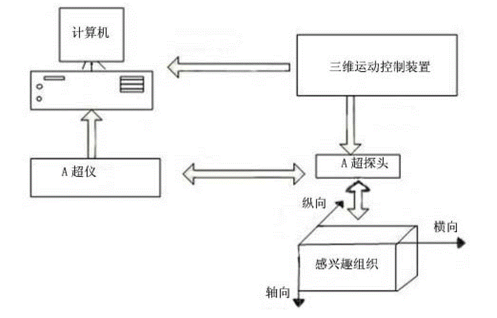
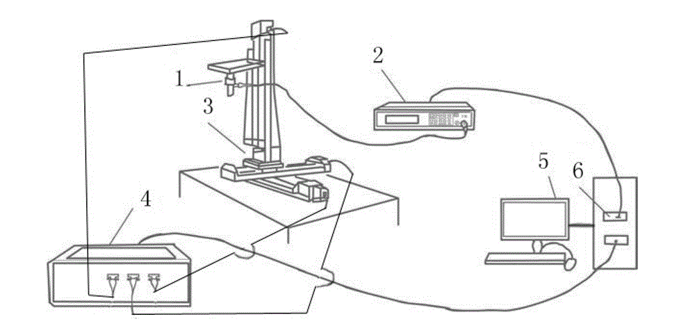
[0038] Such as figure 1 and figure 2 As shown, a mechanical scanning-based A superelastic imaging system includes a three-dimensional motion control device, an A-ultrasonic probe 1, an A-ultrasound instrument 2 and a computer that are electrically connected in turn, and the computer includes a display 5 and a host computer 6. The three-dimensional The motion control device includes a console 3 and a control box 4 , and the control box 4 is connected to a host computer 6 .

[0039] The control box 4 has output terminals in three directions of movement of X, Y and Z axes, and the console 3 has input terminals in three directions of movement of X, Y and Z axes. The X, Y and Z axes of the control box 4 The Z-axis output ends are respectively connected to the console X, Y and Z-axis input ends, the output ends are connected to the input ends through lead wires, the console has a stepping motor, and the bottom of the console is provided with a shock absorber, so The console inclu...

Embodiment 2

[0055] Such as figure 1 and figure 2 Shown, a kind of A superelasticity imaging system based on mechanical scanning comprises three-dimensional motion control device, A supersonic probe 1, A supersonic instrument 2 and computer that are electrically connected in turn, and said computer includes a monitor 5 and a host computer 6 connected to each other, The three-dimensional motion control device includes a console 3 and a control box 4 , and the control box 4 is connected to a host computer 6 .

[0056] The control box 4 has output terminals in three directions of movement of X, Y and Z axes, and the console 3 has input terminals in three directions of movement of X, Y and Z axes. The X, Y and Z axes of the control box 4 The Z-axis output ends are respectively connected to the console X, Y and Z-axis input ends, the output ends are connected to the input ends through lead wires, the console has a stepping motor, and the bottom of the console is provided with a shock absorber...


PUM


Abstract

The invention provides an A-mode ultrasonic elastic imaging system based on mechanical scanning. The A-mode ultrasonic elastic imaging system comprises a three-dimensional motion control device, an A-mode ultrasonic probe, an A-mode ultrasonic instrument and an ultrasonic imaging device, wherein the A-mode ultrasonic instrument controls the A-mode ultrasonic probe to generate ultrasonic signals and receive ultrasonic echo signals; the three-dimensional motion control device drives the A-mode ultrasonic probe to mechanically scan an interesting tissue; and the ultrasonic imaging device re-establishes a two-dimensional or three-dimensional thromboelastogram. An imaging method of the A-mode ultrasonic elastic imaging system based on the mechanical scanning comprises the following steps of: step 1, squeezing the interesting tissue by the A-mode ultrasonic probe under different pressures, sending the ultrasonic signals, and mechanically scanning each point inside the interesting tissue twice, so as to form secondary ultrasonic echo signals; and step 2, re-establishing the two-dimensional or three-dimensional thromboelastogram of the interesting tissue by the ultrasonic imaging device according to elastic deformation amounts of the interesting tissue under the different pressures twice. The A-mode ultrasonic elastic imaging system has the advantages of high positioning precision, high sensitivity, high image resolution, strong practical applicability, wide application range and the like.

Description

technical field [0001] The invention relates to an ultrasonic elastography technology, in particular to a mechanical scanning-based A superelastic imaging system and method thereof. Background technique [0002] Ultrasound elastography is to obtain the waveform of ultrasonic echo signals under two different pressures at the same position in the region of interest through the probe, and use the two echo signals to perform correlation calculations to obtain the corresponding tissue elastic strain. Generally speaking, the probe scanning The pressure on the tissue, the speed of movement and the scanning direction will all have a certain impact on the elastography. For example, if the moving speed is too fast, the displacement and deformation of the tissue will be increased; if the pressure is too small, the displacement and deformation of the tissue will be reduced. Therefore, elastography must consider the impact of the three factors of probe scanning speed, scanning direction...

Claims


Application Information

Patent Timeline
IPC IPC(8): A61B8/14
Inventor 黄庆华叶鹏飞韦岗林春漪
Owner SOUTH CHINA UNIV OF TECH
Why Eureka
Try Eureka