Automatic-jacking tailstock capable of rapidly moving

A fast-moving and tailstock technology, which is applied in the direction of tailstock/top, toolholder accessories, turning equipment, etc., can solve the problems of tailstock waste time, affect processing efficiency, and tailstock takes up a lot of space, so as to improve work efficiency. Efficiency, convenient loading and unloading of workpieces, and time-saving effect

Inactive Publication Date: 2013-02-06
SHANDONG LUNAN MACHINE TOOL
View PDF6 Cites 3 Cited by
  • Summary
  • Abstract
  • Description
  • Claims
  • Application Information

AI Technical Summary

Problems solved by technology

[0002] Pneumatic tailstock tightening is one of the devices often used in machining. The existing automatic tailstock tightening is a structure in which the tailstock body moves axially along the tailstock sleeve or tightens axially. When processing thin and thin-walled pipe fittings clamped on

Method used


Image

  • Automatic-jacking tailstock capable of rapidly moving
  • Automatic-jacking tailstock capable of rapidly moving

Examples


Example Embodiment

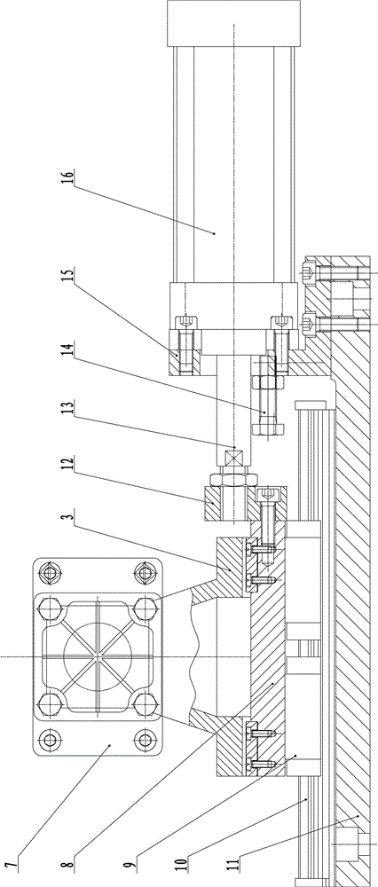
[0017] The present invention will be further described below in conjunction with the drawings and specific embodiments:

[0018] A fast-moving automatic tightening tailstock, such as figure 1 with figure 2 As shown, the bottom plate 11 includes a linear slide rail 10 fixedly connected to the bottom plate 11, a movable cylinder 16 is fixedly connected to one end of the bottom plate 11, the movable cylinder 16 has a movable cylinder piston rod 13, and the center line of the movable cylinder piston rod 13 and the linear slide rail The direction of 10 is parallel, the free end of the piston rod 13 of the moving cylinder is fixedly connected with a tail seat backing plate 8, and a slider 9 is fixedly connected under the tail seat backing plate 8. The sliding block 9 is slidably connected to the linear slide rail 10, and the tail seat backing plate 8 The tailstock body 3 is fixedly connected to the top, the tailstock body 3 is hollow, the tailstock sleeve 2 is slidably connected to th...


PUM


Abstract

The invention discloses an automatic-jacking tailstock capable of rapidly moving, which has the advantages that the use is convenient and the working efficiency is greatly improved. The automatic-jacking tailstock comprise a bottom plate, wherein a linear slide rail is fixedly connected to the bottom plate; a moving cylinder is fixedly connected to one end of the bottom plate and is provided with a moving cylinder piston rod; the central line of the moving cylinder piston rod is parallel to the walking direction of the linear slide rail; a tailstock backing plate is fixedly connected to the free end of the moving cylinder piston rod; a slide block is fixedly connected below the tailstock backing plate; the slide block is connected with the linear slide rail in a sliding manner; a tailstock body is fixedly connected to the tailstock backing plate; the tailstock body is hollow; a tailstock sleeve is connected in the tailstock body in a sliding manner; a jacking cylinder is fixedly connected to the rear end of the tailstock body and is provided with a jacking cylinder piston rod; the free end of the jacking cylinder piston rod is fixedly connected with the rear end of the tailstock sleeve; a tip is sleeved at the front end of the tailstock sleeve; and the contact surface of the tip and the tailstock sleeve is conical. The free end of the moving cylinder piston rod is connected with the tailstock backing plate via a connecting block.

Description

technical field [0001] The invention relates to an automatic tightening tailstock structure, in particular to a fast-moving automatic tightening tailstock. Background technique [0002] Pneumatic tailstock tightening is one of the devices often used in machining. The existing automatic tailstock tightening is a structure in which the tailstock body moves axially along the tailstock sleeve or tightens axially. When processing thin and thin-walled pipe fittings clamped on the mandrel, the tailstock needs to move a long distance to replace the workpiece, and the tailstock also takes up a lot of space, and the operation of the upper and lower parts is inconvenient, and the long-distance movement of the tailstock is wasteful. It takes time and affects the processing efficiency. Contents of the invention [0003] The object of the present invention is to provide a fast-moving automatic tightening tailstock which is easy to use and greatly improves work efficiency. [0004] To ...

Claims


Application Information

Patent Timeline
IPC IPC(8): B23B23/00
Inventor 赵志国张志强陈兆文邱伟
Owner SHANDONG LUNAN MACHINE TOOL
Why Eureka
Try Eureka