Low-resistance warp yarn lubricating device

A technology of lubricating device and warp yarn is applied in the field of yarn lubricating device in the textile field. The effect of reducing influence, reducing friction

Inactive Publication Date: 2013-02-06
WUJIANG KESHIDA TEXTILE
View PDF6 Cites 0 Cited by
  • Summary
  • Abstract
  • Description
  • Claims
  • Application Information

AI Technical Summary

Problems solved by technology

Because the warp yarn moves under the drive of the traction roller, it has a certain tension and the movement path is long, which is prone to yarn breakage and affects work efficiency and product quality.
The traditional method achieves the purpose of lubricating the warp yarn by directly spraying lubricating oil and manually contacting the warp yarn with a lubricating body containing grease. There are disadvantages that the amount of oil and the uniformity of lubrication are not easy to control, and the work efficiency is low.

Method used


Image

  • Low-resistance warp yarn lubricating device
  • Low-resistance warp yarn lubricating device
  • Low-resistance warp yarn lubricating device

Examples


Embodiment 1

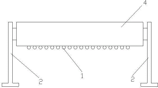
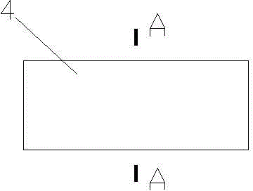
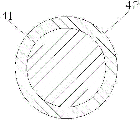
[0020] Example 1: Such as Figure 1-3 As shown, a low-resistance warp lubricating device includes two longitudinally extending brackets 2 on which a cylindrical lubricating body 4 extending laterally is provided. The lubricating body 4 is a rotatable lubricating roller shaft connected to the two supports 2. The lubricating body 4 includes an inner core 41 and a lubricating layer 42 wrapped on the outside of the inner core 41. The lubricating layer 42 is linoleum with a thickness of 5-20 times the diameter of the lubricated warp yarn 1 to ensure that the lubricating oil content in the linoleum is moderate. To ensure the lubrication effect of the warp yarn 1, and avoid the pollution and resistance increase caused by the excessive oil, and prevent the linoleum from being damaged due to the thinning of the linoleum and the warp yarn 1 and the friction for a short time, which can ensure the service life of the linoleum. The way that the linoleum absorbs the lubricating oil can be s...

Embodiment 2

[0021] Embodiment 2: The difference from Embodiment 1 is that the lubricating layer 42 is a solid paraffin layer, which avoids the problem of controlling the amount of oil when using liquid lubricating oil. Compared with liquid lubricating oil, it is easier to keep the warp yarn 1 clean. The outer side of the inner core 41 is provided with a groove 6, and the solid paraffin layer 42 is arranged in the groove 6, which is convenient for replacement. For example, when the warp yarn 1 causes more and deeper scratches and affects normal lubrication, replace it. Replace it later. The thickness of the lubricating layer 42 is 5-10 times the diameter of the warp yarn 1, achieving a balance between the lubricating effect and the service life.


PUM


Abstract

The invention relates to a low-resistance warp yarn lubricating device, which includes two vertically extending brackets, and is characterized in that a transversely extending cylindric lubricating body is arranged on the two brackets. The low-resistance warp yarn lubricating device adopts the cylindric lubricating body to be contacted with warp yarn, so as to be used for lubrication; as the lubricating body is contacted with each warp yarn at one point, the friction is greatly reduced, excessive resistance adding to the motion of warp yarns caused by mounting of the lubricating device is avoided to reduce influence on normal weaving; and further, a rotary lubricating roller serves as the lubricating body to replace sliding friction with rolling friction, as a result, more resistance is reduced, and the lateral surface of the entire lubricating body serves as an oil feeding surface or grease feeding surface to enlarge the oil feeding area and the grease feeding area and prolong the usage duration of oil grease one-time stored in the lubricating body.

Description

Technical field [0001] The invention relates to a lubricating device for yarns in the textile field, in particular to a lubricating device for warp yarns of an air jet loom. Background technique [0002] Air jet loom is a shuttleless loom that uses jet air to draw the weft through the shed. Because the warp yarn moves under the drive of the traction roller, it has a certain tension, and the movement path is long. It is easy to break the yarn and affect the work efficiency and product quality. The traditional method achieves the purpose of lubricating the warp yarn by directly spraying lubricating oil and manually contacting the warp yarn with a grease-containing lubricating body, which has the disadvantages that the oil amount and lubrication uniformity are not easy to control, and the work efficiency is low. Summary of the invention [0003] The present invention overcomes the shortcomings of the prior art and provides a warp lubricating device with simple structure, convenient ...

Claims


Application Information

Patent Timeline
Patent Type & Authority Applications(China)
IPC IPC(8): D03J1/02
Inventor 庄郁峰
Owner WUJIANG KESHIDA TEXTILE
Why Eureka
Try Eureka