Solar photovoltaic tile and manufacture method thereof
A solar photovoltaic and solar cell technology, applied in the direction of photovoltaic modules, photovoltaic power generation, photovoltaic module support structures, etc., can solve the problems of low production efficiency of solar photovoltaic tiles, poor heat dissipation effect of photovoltaic tiles, and poor connection reliability, so as to reduce construction costs. The effect of using energy consumption, reducing the amount of colloid used, and ensuring sealing performance
- Summary
- Abstract
- Description
- Claims
- Application Information
AI Technical Summary
Problems solved by technology
Method used
Image
Examples
Embodiment 1
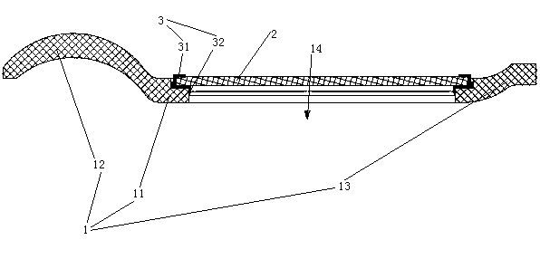
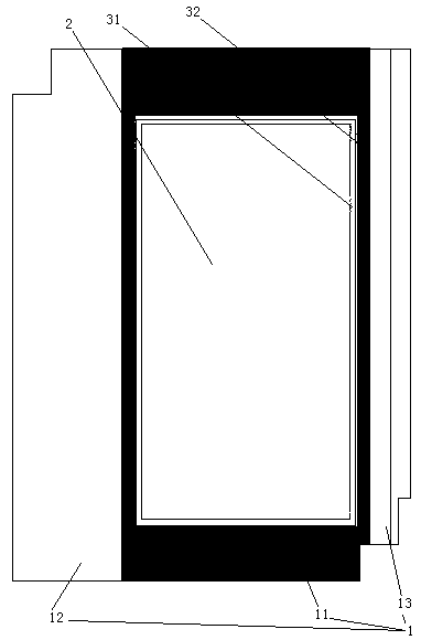
[0054] Embodiment one, see figure 1 , a solar photovoltaic tile, including a substrate 1, a solar cell 2 and an adhesive layer 3.
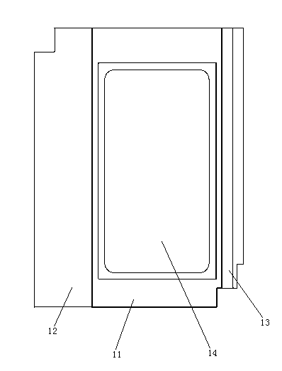
[0055] The substrate 1 includes a substrate main body 11 , an upper cover edge 12 located on the left edge of the substrate main body 11 and a lower cover edge 13 located on the right edge of the substrate main body 11 . The upper cover edge 12 is arched. The upper cover edge 12, the substrate body 11 and the lower cover edge 13 form a groove structure.
[0056] The clip body 11 is provided with a through hole 14 passing through the upper and lower surfaces of the substrate. The through hole 14 is a stepped hole with a large opening at the upper end and a small opening at the lower end. The solar cell 2 rests on the step of the through hole 14 and is bonded to the substrate 1 through the adhesive layer 3 .
[0057] The adhesive layer 3 includes a butyl hot melt adhesive layer 31 and a silica gel layer 32 . Both the butyl hot melt adhesive lay...
Embodiment 2
[0074] Embodiment two, see Figure 10 , The difference with the first embodiment is: a light-gathering groove 15 is provided on the left and right sides of the upper cover edge 12 . The cross-section of the light-gathering groove 15 is arc-shaped. The upper surface of the solar cell 2 is flush with the upper surface of the substrate main body 11 .
[0075] In step 107, the upper surface of the upper cover edge 12 and the upper surface of the lower cover edge 13 are coated with white matt glaze to form white straight stripes. The purpose of coating the white matt glaze is to improve the reflective effect of the white grain.
[0076] In step 104, the mold for making the substrate is heated to 320° C. and kept warm for 7 minutes.
[0077] see Figure 11 , during use, the light collecting groove 15 reflects the light 7 to form a light band 8 above the substrate main body 11 .
[0078] In the above embodiments, the zebra patterns arranged on the upper surface of the substrate ...
PUM
| Property | Measurement | Unit |
|---|---|---|
| thickness | aaaaa | aaaaa |
Abstract
Description
Claims
Application Information
 - R&D
- Intellectual Property
- Life Sciences
- Materials
- Tech Scout
- Unparalleled Data Quality
- Higher Quality Content
- 60% Fewer Hallucinations
Browse by: Latest US Patents, China's latest patents, Technical Efficacy Thesaurus, Application Domain, Technology Topic, Popular Technical Reports.
© 2025 PatSnap. All rights reserved.Legal|Privacy policy|Modern Slavery Act Transparency Statement|Sitemap|About US| Contact US: help@patsnap.com


