A pin roller type pinion device

A technology of gear devices and rollers, which is applied to transmission devices, friction transmission devices, transmission device parts, etc., can solve the problems of gear loss of rotational motion, ability to reduce load, and degradation of transmission accuracy between gears and racks, etc.

Inactive Publication Date: 2013-02-06
KAMOSEIKO
View PDF1 Cites 8 Cited by
  • Summary
  • Abstract
  • Description
  • Claims
  • Application Information

AI Technical Summary

Problems solved by technology

[0010] Once the outer circumference 52a is deformed, this deformation deteriorates the transmission accuracy between the gear and the rack, so that the gear loses its smooth rotational motion to cause an unacceptable noise level when transmitting the rotation to the rack
[0011] With such deterioration in transmission accuracy, wear between the gear and the rack develops, thereby reducing the ability of the rack to withstand the load from the gear, resulting in failure that results in shortened service life

Method used


Image

  • A pin roller type pinion device
  • A pin roller type pinion device
  • A pin roller type pinion device

Examples


Embodiment Construction

[0039] In the embodiments described in detail below, the same reference numerals are used to represent the same types of technical features, and the positions and directions of different elements are used corresponding to the left, right and upper and lower sides in the drawings of each embodiment of the present invention.

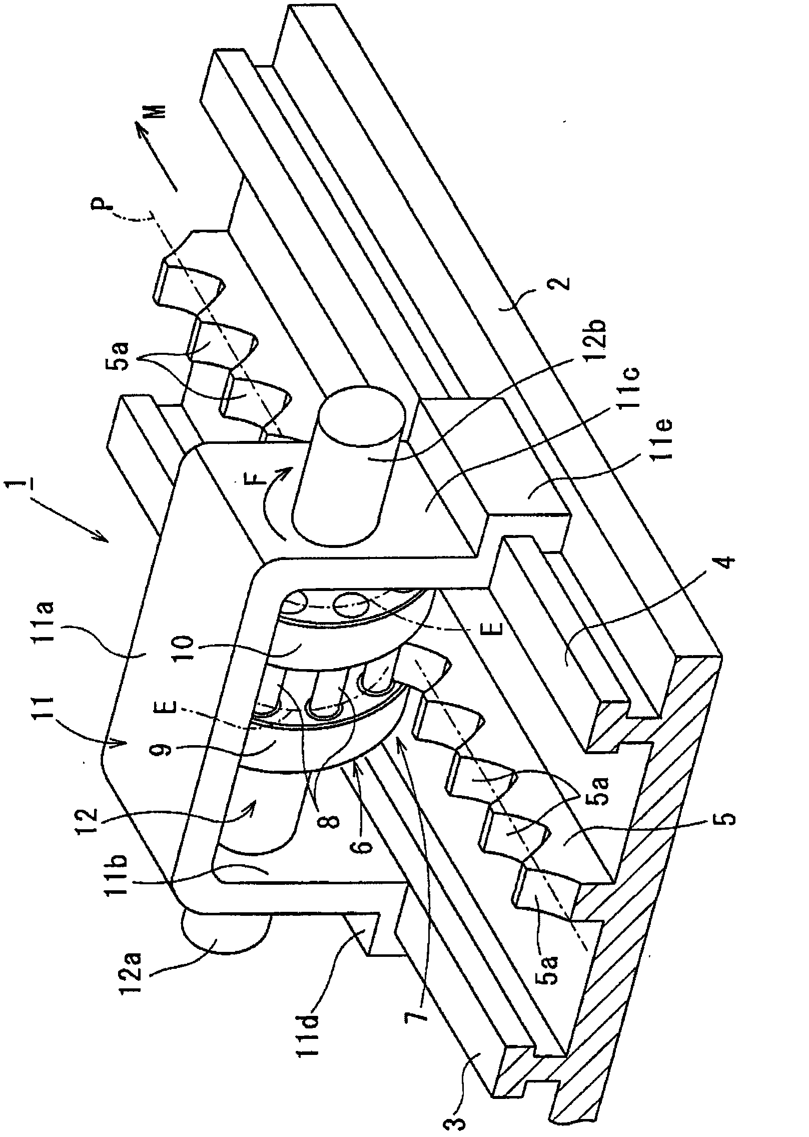
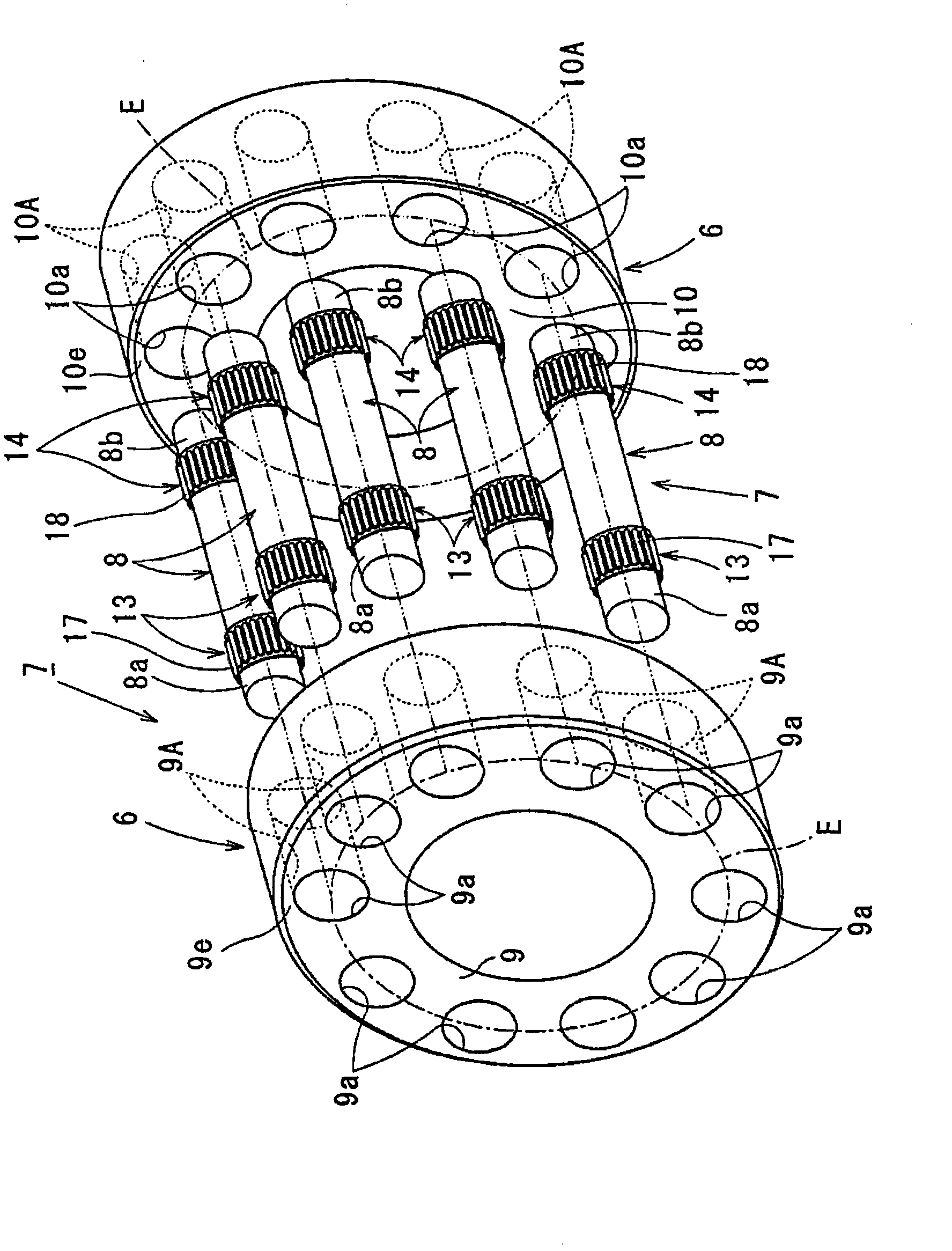
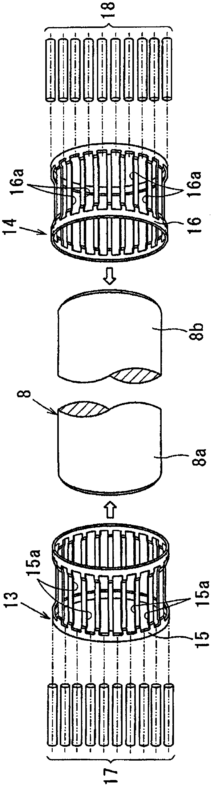
[0040] refer to Figure 1 to Figure 7 , which shows a roller gear device 7 according to a first embodiment of the present invention, as figure 1 Shown, for example, is a rack-and-pinion arrangement 1 with a base plate 2 placed on the floor (not shown) in an assembly plant.

[0041] On the left and right side of the base plate 2 guide rails 3 , 4 are arranged, each guide rail having a T-shaped section. In the middle of the base plate 2 between the guide rails 3, 4, a linear gear 5 is arranged in the longitudinal direction M thereof.

[0042] The length of the rack 5 is determined to satisfy the object used, and the upper surface of the rack 5 has a plura...


PUM


Abstract

In a pin roller type pinion device (7), a first bearing (13) has first pin needles (17) rollably arranged around pin rollers (8) between an inner surface of first circular holes (9A) and one end portion (8a) of the pin rollers (8). A second bearing (14) has second pin needles (18) rollably arranged around the pin rollers (8) between an inner surface of second circular holes (10a) and the other end portion (8a, 8b) of the pin rollers (8). This prevents an external pressure from developing on the inner surface (9A, 10A) of the circular holes (9a, 10a) when inserting the pin needles (17, 18) between the inner surface (9A, 10A) of the circular holes (9a, 10a) and the end portions (8a, 8b) of the pin rollers (8). Deformation subjected to the first and second disc plates (9, 10) can be prevented, transmission precision between the pinion (6) and the rack (5) can be ameliorated, therefore excellent transmission between the pinion and the rack can be kept, and the service life can be prolonged.

Description

technical field [0001] The present invention relates to a roller-type gear arrangement in which a gear has a plurality of rollers, some of which mesh with a spur rack, and more particularly to a roller-type gear having a bearing for rotatably supporting the rollers device. Background technique [0002] A rack incorporating a gear is known as a rack and pinion steering device, a rack and pinion device, or a torque converting device, the latter being disclosed in Korean Patent No. 10-0945193. [0003] In the torque converting device, a plurality of pins are arranged between a first disc and a second disc to form a gear. Make the gear into the state of meshing with the spur rack, so as to move along the rack along with the rotational movement of the gear. This makes it possible to form a low-noise, low-vibration rack-and-pinion structure with minimum runout and low transmission losses. [0004] Rack and pinion structures have been effectively used in the field of manufacturi...

Claims


Application Information

Patent Timeline
Patent Type & Authority Applications(China)
IPC IPC(8): F16H19/04F16H57/00F16C19/22
CPCF16H19/04F16H57/00F16H55/10F16C19/22F16C19/463F16C33/52F16C33/543F16C2240/84Y10T74/19981F16H19/02
Inventor 今濑宪司
Owner KAMOSEIKO
Why Eureka
Try Eureka