Collector with real-time monitoring function

A real-time monitoring and collector technology, applied in the direction of measuring devices, scientific instruments, suspension and porous material analysis, etc., can solve complex and cumbersome problems, and achieve the effect of real-time monitoring and monitoring results

Active Publication Date: 2013-02-06
DONGGUAN HUIHAI ENVIRONMENTAL PROTECTION TECH
View PDF5 Cites 21 Cited by
  • Summary
  • Abstract
  • Description
  • Claims
  • Application Information

AI Technical Summary

Problems solved by technology

[0004] The above-mentioned process of weighing, analyzing and calculating the collected particles is complex and cumbersome. Therefore, it is necessary to develop a new technical solution to solve the above problems

Method used


Image

  • Collector with real-time monitoring function
  • Collector with real-time monitoring function
  • Collector with real-time monitoring function

Examples


Embodiment Construction

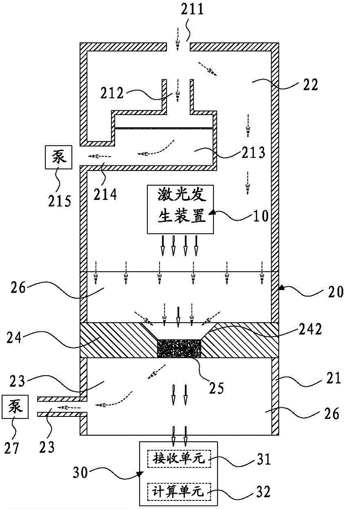
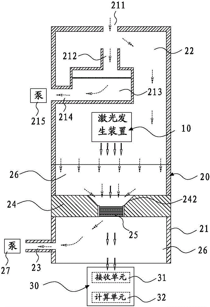
[0044] Please refer to figure 1 As shown, it shows the specific structure of a preferred embodiment of the present invention, including a laser emitting device 10 , a fine particle collection device 20 and a laser receiving device 30 .

[0045] Wherein, the fine particle collection device 20 includes a housing 21, a classification channel 213 and a sampling channel 26 arranged in the housing 21 apart from each other;

[0046] The top of the housing 21 is provided with a general air inlet 211, and the two ends of the classification channel 213 are respectively formed with a first air inlet 212 and a first air outlet 214, and the first air inlet 212 is arranged at a distance between the main air inlet 211. Below and opposite to the total air inlet 211, the projection area of ​​the total air inlet 211 projected on the plane where the first air inlet 212 is located in the vertical direction is completely located in the first air inlet 212; A first collection unit for collecting c...


PUM


Abstract

The invention discloses a collector with a real-time monitoring function. The collector comprises a laser emission device, a fine particle collecting device and a laser receiving device, wherein the fine particle collecting device comprises a shell, a sampling channel and a grading channel; the sampling channel and the grading channel are separately arranged in the shell; the grading channel is used for firstly grading the particles for the gas entering into the shell; the bigger particles are drained from the grading channel; to-be-monitored fine particles enter into the sampling channel; a barrier plate is arranged in the sampling channel; a flow-guiding hole is arranged on the barrier plate; a second collecting unit for collecting the fine particles is arranged in the flow-guiding hole; the laser emission device is located right above the flow-guiding hole; a receiving unit of the laser receiving device is located right under the flow-guiding hole; a laser beam emitted from the laser emission device passes through the second collecting unit and then enters into the receiving unit of the laser receiving device; and a calculating unit of the laser receiving device is used for calculating the concentration of the fine particles collected on the second collecting unit according to a light intensity signal measured by the receiving unit.

Description

technical field [0001] The invention relates to the technical field of equipment for sampling particles in the atmosphere, in particular to a collector with a real-time monitoring function. Background technique [0002] With the development of industry, the level of particulate pollutants in the atmosphere is increasing. These particulate pollutants will absorb various harmful substances in the air that can damage the nervous system and cause cancer, and bring many negative effects to the environment and human health. How to classify and calibrate the particle size of the particulate matter in the atmosphere is the primary problem in the research and solution of atmospheric particulate matter pollution. [0003] People use the particle sampling system to obtain the corresponding level of particulate matter in the air, so as to effectively detect and analyze the air quality or pollution index. Usually, an impactor sampler is used to carry out particle size classification sam...

Claims


Application Information

Patent Timeline
Patent Type & Authority Applications(China)
IPC IPC(8): G01N15/06G01N1/22
Inventor 白云鹤范洪波段广亮肖丽莎王莘
Owner DONGGUAN HUIHAI ENVIRONMENTAL PROTECTION TECH
Why Eureka
Try Eureka