Connector

A connector and housing technology, applied in the direction of connection, connecting device components, coupling devices, etc., can solve the problems of the connector housing becoming larger and the durability of the locking arm being reduced, and achieving smooth durability and good locking feeling. Effect

Active Publication Date: 2013-02-06
YAZAKI CORP
View PDF6 Cites 6 Cited by
  • Summary
  • Abstract
  • Description
  • Claims
  • Application Information

AI Technical Summary

Problems solved by technology

However, due to this cantilever structure, the durability of the lock arm decreases, and it is necessary to secure a space for bending the lock arm in a large amount, so that the connector housing becomes large

Method used


Image

  • Connector
  • Connector
  • Connector

Examples


Embodiment Construction

[0030] Hereinafter, illustrative embodiments of the present invention will be described with reference to the accompanying drawings.

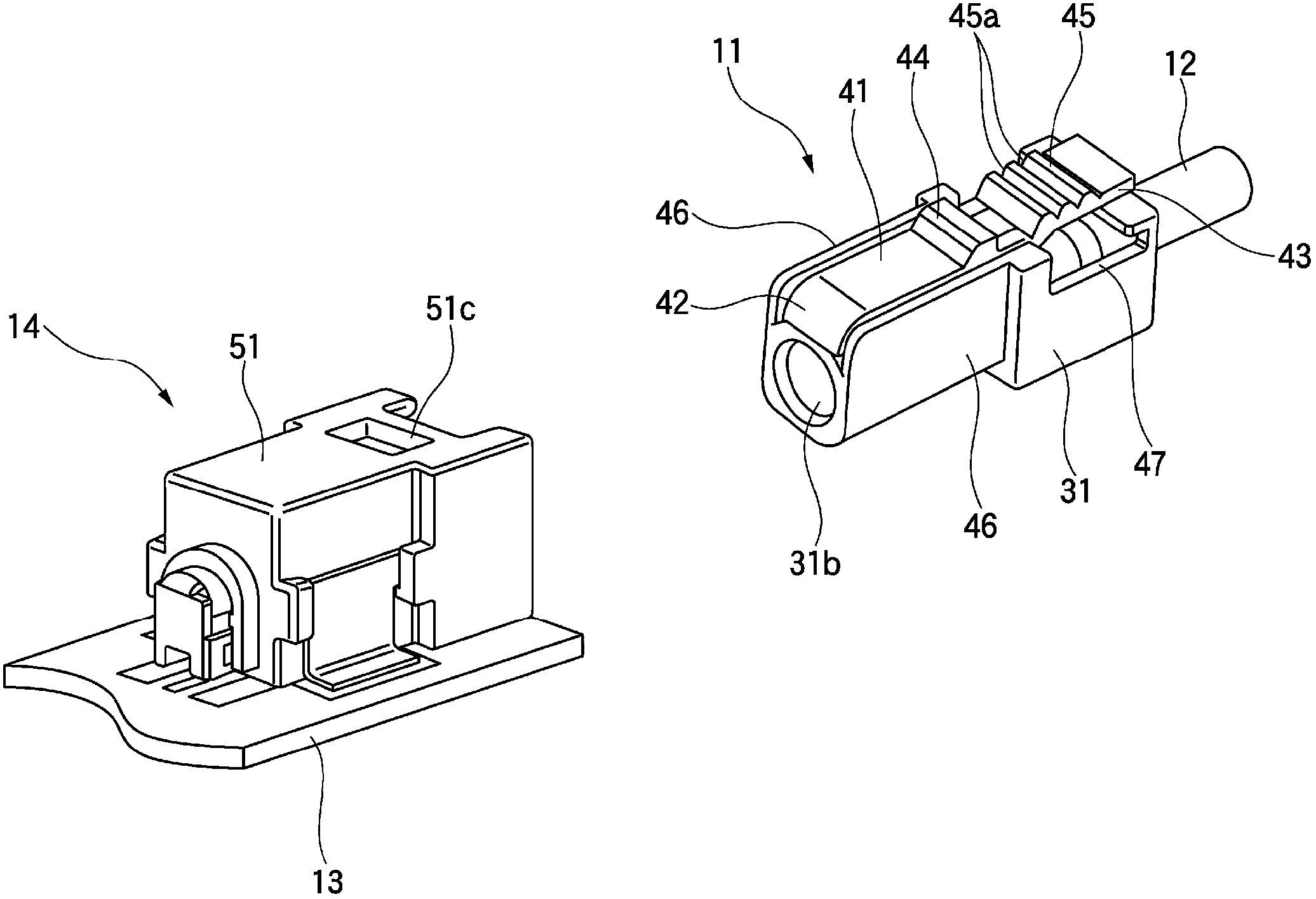
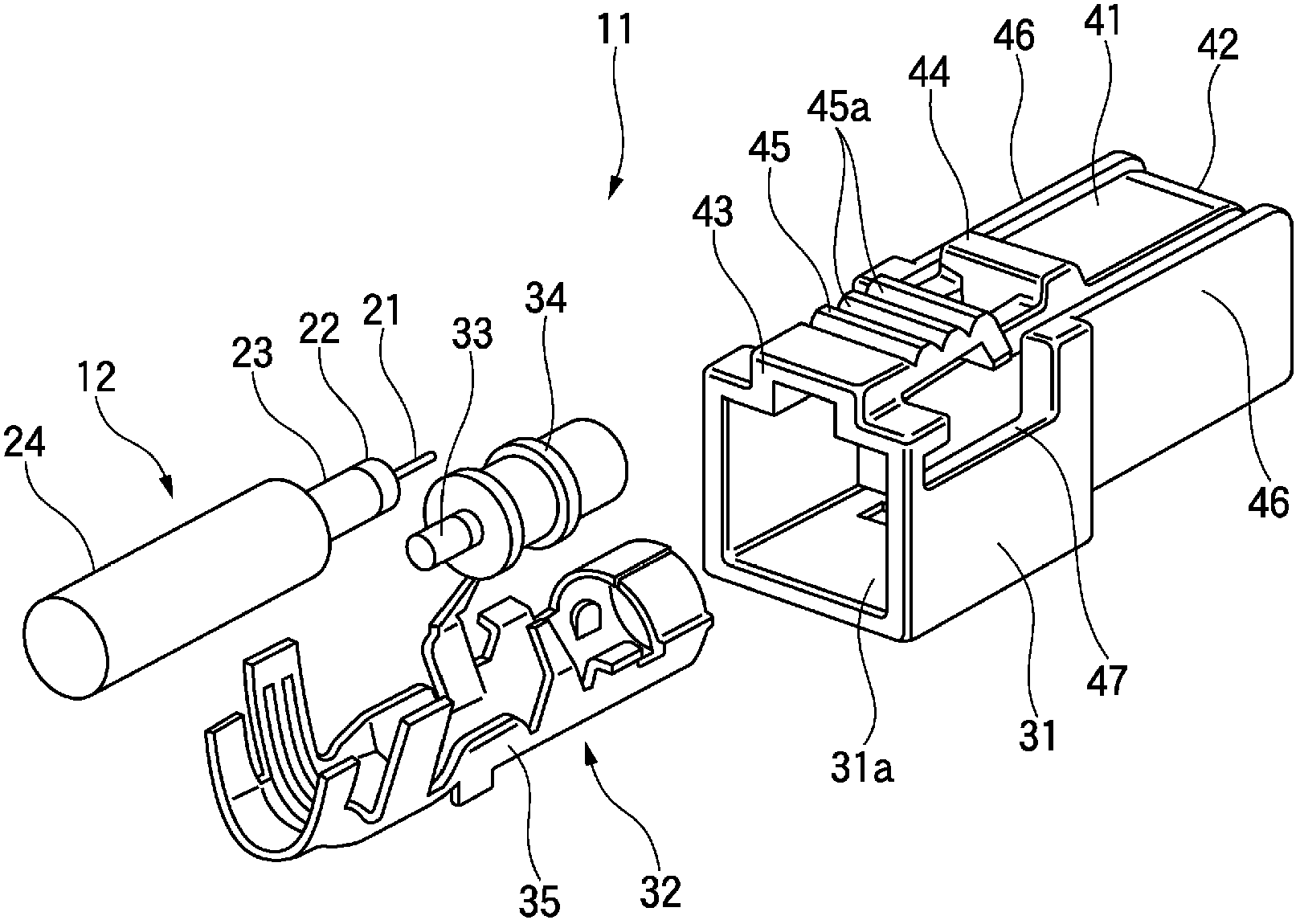
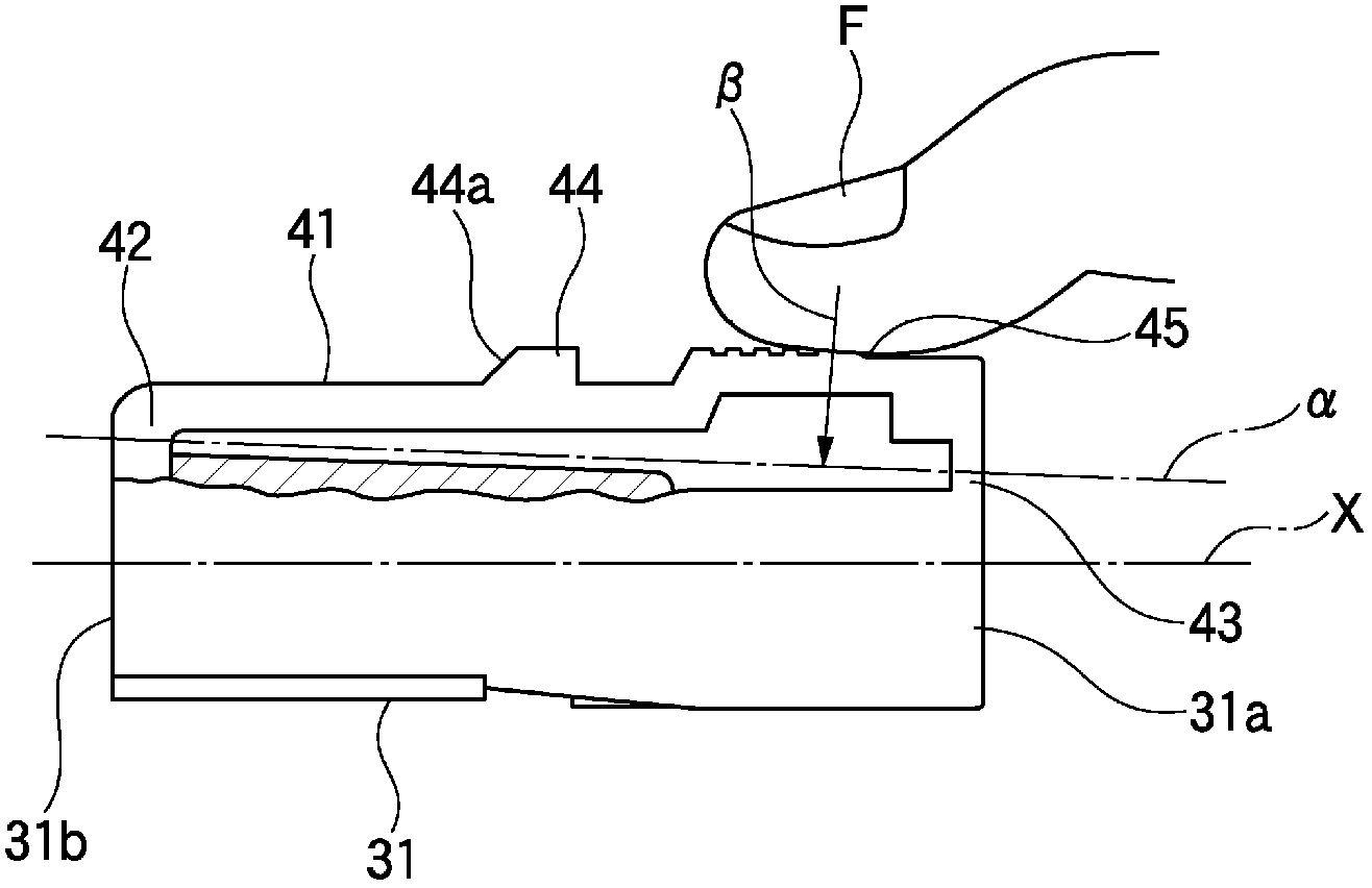
[0031] figure 1 is a perspective view of a cable side connector and a substrate connector connected to the cable side connector according to an illustrative embodiment, figure 2 is an exploded perspective view of a cable side connector according to an illustrative embodiment, image 3 is a housing side view of a cable side connector according to an illustrative embodiment, Figure 4 is an exploded perspective view of the board connector connected to the cable side connector, and Figure 5A to Figure 5C is a schematic side cross-sectional view showing the movement that occurs when the cable-side connector is inserted into and pulled out from the board connector.

[0032] Such as figure 1 As shown in , a cable-side connector (connector) 11 according to an illustrative embodiment is a shielded connector attached to an end of a shielded cabl...


PUM


Abstract

There is provided a connector. A lock arm is connected at a leading end-side and a rear end-side of a housing, supported at both ends thereof along an insertion/pulling out direction with respect to an opposite connector housing, and elastically deformable with the connection parts with the housing serving as fulcrums. A locking claw is formed at the lock arm and locked into a locking hole of the opposite connector housing when inserting the housing into the opposite connector housing. The lock arm has a lock release part which releases a locked state of the locking claw to the locking hole by being pressed toward the rear end-side beyond the locking claw. A position of the fulcrum at the rear end-side is arranged at an opposite side to a protruding direction of the locking claw, compared to a position of the fulcrum at the leading end-side.

Description

[0001] The entire disclosure of Japanese Patent Application No. 2011-164624 filed on Jul. 27, 2011 including specification, drawings and claims is incorporated herein by reference in its entirety. technical field [0002] The present invention relates to a connector that is plugged into and unplugged from a counter connector. Background technique [0003] Such as Figure 10 As shown in , there is known a lock mount connector having at its upper portion: a lock projection 1 which locks a lock opening of the opposite connector housing; and a lock release portion 2 which is used to release the Relative to the locked state of the connector housing, and wherein the locking arm 4 of the two-end support structure that makes the front and rear ends fixed on the connector housing 3 is arranged on an outer wall surface of the connector housing 3 (for example, refer to the patent document 1). [0004] In the above connector, the rear end portion of the lock arm 4 is folded back to for...

Claims


Application Information

Patent Timeline
Patent Type & Authority Applications(China)
IPC IPC(8): H01R13/639H01R13/46
CPCH01R13/6272
Inventor 宫胁孝治
Owner YAZAKI CORP
Why Eureka
Try Eureka