Frequency multiplier type booster circuit, control method and inverter thereof

A technology of a booster circuit and a control method, which is applied to the control of a frequency-doubling booster circuit and the field of a frequency-doubling booster circuit, can solve the problems of shortening the life of the device, increasing the circuit current ripple, and increasing the heat generation of the switch tube. , to achieve the effect of improving power conversion efficiency, improving current ripple and prolonging service life

Active Publication Date: 2013-02-06
TBEA SUNOASIS +1
View PDF5 Cites 8 Cited by
  • Summary
  • Abstract
  • Description
  • Claims
  • Application Information

AI Technical Summary

Problems solved by technology

It can be seen that in order to improve the efficiency of the three-level inverter, the operating frequency of its boost circuit needs to be increased, so it is necessary to increase the operating frequency of the switching tube in the boosting circuit at the same time, but this will cause the switching tube to fail. A series of problems such as increased heat, increased current ripple in the circuit, and shortened device life. At the same time, because the switch tube always works at high frequency, the switching loss is serious, and even damage occurs, which affects the normal operation of the circuit.

Method used


Image

  • Frequency multiplier type booster circuit, control method and inverter thereof
  • Frequency multiplier type booster circuit, control method and inverter thereof
  • Frequency multiplier type booster circuit, control method and inverter thereof

Examples


Embodiment 1

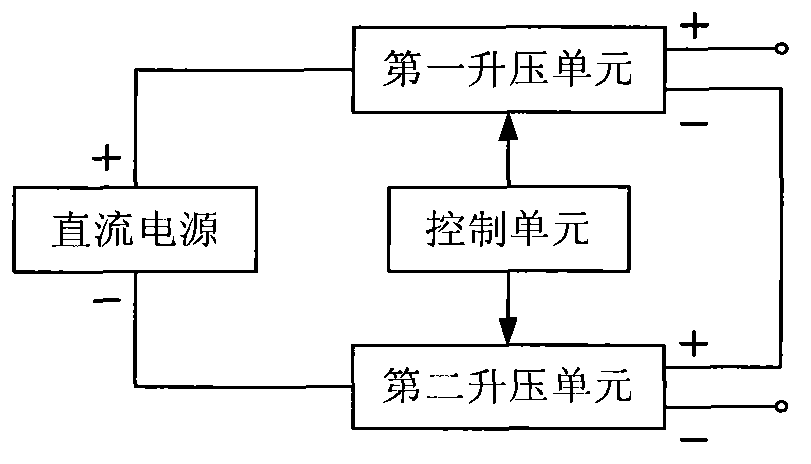
[0045] Such as figure 1 As shown, this embodiment provides a frequency multiplication boost circuit, which includes a DC power supply, a first boost unit, a second boost unit, and a control unit.

[0046] The input terminal of the first boost unit is connected to the positive pole of the DC power supply, the negative output terminal of the first boost unit is connected to the positive output terminal of the second boost unit; the input terminal of the second boost unit is connected to the DC power supply. The negative pole of the power supply is connected; the control unit is respectively connected with the first boost unit and the second boost unit.

[0047] Both the first boost unit and the second boost unit are used to increase the output voltage value of the frequency multiplier boost circuit; the control unit is used to separately perform the first boost unit and the second boost unit Control so that the output voltage value of the first boost unit is equal to the output...

Embodiment 2

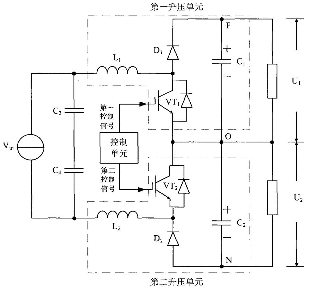
[0050] Such as figure 2 As shown, this embodiment provides a frequency multiplication boost circuit, which includes a DC power supply V in , a first boost unit, a second boost unit and a control unit.

[0051] The first boost unit includes a first inductor L 1 , the first switch tube VT 1 , the first diode D 1 and the first capacitor C 1 .

[0052] The first inductance L 1 respectively with the DC supply V in The anode and the first switching tube VT 1 The drain is connected, the first switching tube VT 1 The grid of the control unit is connected, and the first switching tube VT 1 source of the first capacitor C 1 connected to the negative pole (connection point is O point), the first diode D 1 The cathode and the first capacitor C 1 The anode is connected (the connection point is point P), the first diode D 1 The anode of the first switching tube VT 1 connected to the drain. The first capacitor C 1 The voltage value between the positive and negative poles (be...

Embodiment 3

[0076] Such as Figure 8 As shown, this embodiment provides a control method for the frequency multiplication booster circuit as described in Embodiment 1, and the booster circuit further includes a method for respectively measuring the output voltage value U of the first booster unit 1 and the output voltage value U of the second boost unit 2 The measuring unit, the control method includes the steps of:

[0077] s101. The measuring unit simultaneously measures the output voltage value U of the first step-up unit 1 and the output voltage value U of the second boost unit 2 , and send the measured two voltage values ​​to the control unit in real time.

[0078] s102. The control unit judges the output voltage value U of the first booster unit in real time 1 Is it equal to the output voltage value U of the second boost unit 2 , and control the first boost unit and the second boost unit respectively according to the judgment result, so that the output voltage value U of the fi...


PUM


Abstract

The invention provides a frequency multiplier type booster circuit. The frequency multiplier booster circuit comprises a direct-current power supply, a first booster unit, a second booster unit and a control unit, wherein the input end of the first booster unit is connected with the positive electrode of the direct-current power supply; the negative electrode output end of the first booster unit is connected with the positive electrode output end of the second booster unit; the input end of the second booster unit is connected with the negative electrode of the direct-current power supply; the first booster unit and the second booster unit are used for improving the output voltage value of the frequency multiplier type booster circuit; and the control unit is used for respectively controlling the first booster unit and the second booster unit, so that the output voltage value of the first booster unit is equal to that of the second booster unit. Correspondingly, the invention provides an inverter comprising the frequency multiplier type booster circuit and a control method for the frequency multiplier type booster circuit. The frequency multiplier type booster circuit provided by the invention can reduce switching loss and working frequency, and can improve current ripple.

Description

technical field [0001] The present invention relates to the technical field of electronic power, in particular to a frequency multiplication boost circuit, an inverter including the frequency multiplication boost circuit, and a control method for the frequency multiplication boost circuit. Background technique [0002] Photovoltaic inverter is a device that converts light energy into electrical energy. Its efficiency directly affects the amount of grid-connected power generation, so it is the most critical part of photovoltaic power station power generation. In order to improve the efficiency of photovoltaic inverters, it can be achieved by reducing the loss of power devices, reducing the loss of filter inductors, and improving the efficiency of transformers. Among them, the efficiency of the transformer can only be improved through the use of new materials, new processes and other new technologies by the transformer manufacturer. Therefore, in order to improve the efficienc...

Claims


Application Information

Patent Timeline
Patent Type & Authority Applications(China)
IPC IPC(8): H02M3/155H02M1/14
Inventor 熊俊峰刘伟增刘永奎
Owner TBEA SUNOASIS
Why Eureka
Try Eureka