A frequency multiplier boost circuit, its control method, and inverter
The technology of a boost circuit and control method is applied in the control of frequency multiplier boost circuit and the field of frequency multiplier boost circuit, which can solve the problems of shortened device life, increased circuit current ripple, and increased heat generation of switching tubes, etc. , to achieve the effects of improving power conversion efficiency, increasing operating frequency, and improving current ripple
- Summary
- Abstract
- Description
- Claims
- Application Information
AI Technical Summary
Problems solved by technology
Method used
Image
Examples
Embodiment 1
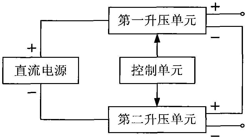
[0045] like figure 1 As shown, this embodiment provides a frequency multiplication boost circuit, which includes a DC power supply, a first boost unit, a second boost unit, and a control unit.
[0046] The input terminal of the first boost unit is connected to the positive pole of the DC power supply, the negative output terminal of the first boost unit is connected to the positive output terminal of the second boost unit; the input terminal of the second boost unit is connected to the DC power supply. The negative pole of the power supply is connected; the control unit is respectively connected with the first boost unit and the second boost unit.
[0047] Both the first boost unit and the second boost unit are used to increase the output voltage value of the frequency multiplier boost circuit; the control unit is used to separately perform the first boost unit and the second boost unit Control so that the output voltage value of the first boost unit is equal to the output vo...
Embodiment 2
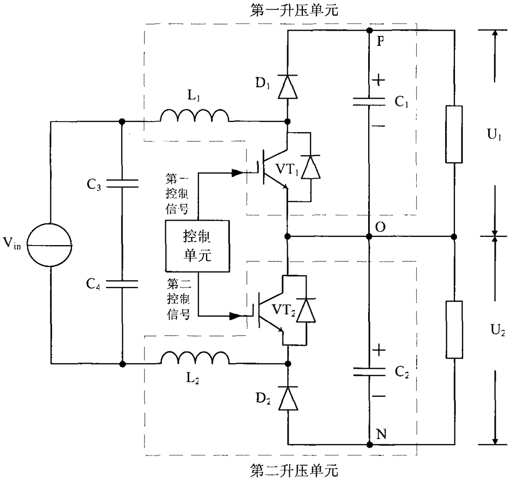
[0050] like figure 2 As shown, this embodiment provides a frequency multiplication boost circuit, which includes a DC power supply V in , a first boost unit, a second boost unit and a control unit.
[0051] The first boost unit includes a first inductor L 1 , the first switch tube VT 1 , the first diode D 1 and the first capacitor C 1 .
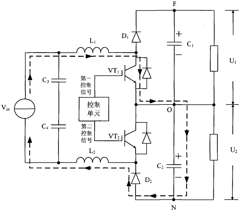
[0052] The first inductance L 1 respectively with the DC supply V in The anode and the first switching tube VT 1 The drain is connected, the first switching tube VT 1 The grid of the control unit is connected, and the first switching tube VT 1 source of the first capacitor C 1 connected to the negative pole (connection point is O point), the first diode D 1 The cathode and the first capacitor C 1 The anode is connected (the connection point is point P), the first diode D 1 The anode of the first switching tube VT 1 connected to the drain. The first capacitor C 1 The voltage value between the positive and negative poles (betwe...
Embodiment 3
[0076] like Figure 8 As shown, this embodiment provides a control method for the frequency multiplication booster circuit as described in Embodiment 1, and the booster circuit further includes a method for respectively measuring the output voltage value U of the first booster unit 1 and the output voltage value U of the second boost unit 2 The measuring unit, the control method includes the steps of:
[0077] s101. The measuring unit simultaneously measures the output voltage value U of the first step-up unit 1 and the output voltage value U of the second boost unit 2 , and send the measured two voltage values to the control unit in real time.
[0078] s102. The control unit judges the output voltage value U of the first booster unit in real time 1 Is it equal to the output voltage value U of the second boost unit 2 , and control the first boost unit and the second boost unit respectively according to the judgment result, so that the output voltage value U of the first...
PUM
 Abstract
Description
Claims
Application Information
 - R&D
- Intellectual Property
- Life Sciences
- Materials
- Tech Scout
- Unparalleled Data Quality
- Higher Quality Content
- 60% Fewer Hallucinations
Browse by: Latest US Patents, China's latest patents, Technical Efficacy Thesaurus, Application Domain, Technology Topic, Popular Technical Reports.
© 2025 PatSnap. All rights reserved.Legal|Privacy policy|Modern Slavery Act Transparency Statement|Sitemap|About US| Contact US: help@patsnap.com


