Crystal oscillator ageing compensation method

A crystal oscillator, aging value technology, used in the field of electronics

Inactive Publication Date: 2013-02-06
BEIJING 7Q TECH
View PDF3 Cites 6 Cited by
  • Summary
  • Abstract
  • Description
  • Claims
  • Application Information

AI Technical Summary

Problems solved by technology

But some applications are not suitable for this method, such as aerospace applications or some equipment and devices that require long-term operation

Method used


Image

  • Crystal oscillator ageing compensation method
  • Crystal oscillator ageing compensation method
  • Crystal oscillator ageing compensation method

Examples


specific example

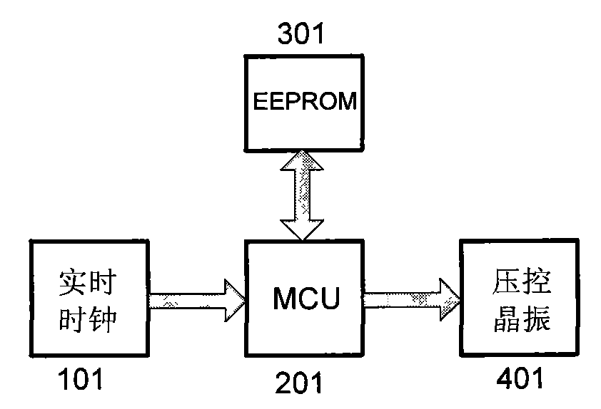
[0017] figure 2 As a specific example of a method for compensating crystal oscillator aging, the example includes:

[0018] The real-time clock is used to generate the current time. By making a difference between the current time and the start time of the crystal oscillator, the usage time of the crystal oscillator can be obtained; EEPROM is used to store the monthly (or annual) aging value of the voltage-controlled crystal oscillator under test. ; MCU, according to the current time generated by the real-time clock, obtains the use time of the voltage-controlled crystal oscillator, and obtains the compensation value according to the aging value stored in the EEPROM, and can perform compensation at intervals according to the setting, and send the compensation value to the voltage control Crystal oscillator; the voltage-controlled crystal oscillator is the compensated part, which is used to generate a more accurate output frequency.

[0019] The following explains its working ...


PUM


Abstract

The invention provides a crystal oscillator ageing compensation method. By the method, crystal oscillator ageing is compensated by the aid of the ageing law of crystal oscillators, and a typical structure consists of a timing device, a computing unit, a storage unit and a crystal oscillator, wherein the timing device is used for recording use time of the crystal oscillator, the computing unit is used for fitting an ageing curve according to the crystal oscillator use time and a storage unit value and generating compensation data, and the storage unit is used for storing ageing values of the crystal oscillator which is a component to be compensated.

Description

technical field [0001] The invention relates to the field of electronic technology, and provides a compensation method for the aging of crystal oscillators, which can be used for aging compensation of various crystal oscillators such as ordinary quartz crystal oscillators, voltage-controlled crystal oscillators, temperature-compensated crystal oscillators, and constant temperature crystal oscillators. Background technique [0002] Quartz crystal oscillator is a high-precision and high-stability oscillator, which is widely used in various oscillating circuits such as televisions and computers, as well as frequency generators in communication systems, generating clock signals for data processing equipment, and generating clock signals for specific systems. Provides a reference signal. The International Electrotechnical Commission defines ordinary crystal oscillators (SPXO), voltage-controlled crystal oscillators (VCXO), temperature-compensated crystal oscillators (TCXO), and o...

Claims


Application Information

Patent Timeline
Patent Type & Authority Applications(China)
IPC IPC(8): H03B5/04G01R31/00
Inventor 不公告发明人
Owner BEIJING 7Q TECH
Why Eureka
Try Eureka