
Circuit for supplying precise low-frequency clock signal, and control method for circuit

A low-frequency clock and calibration circuit technology, applied in electrical components, electrical pulse generation, pulse generation, etc., can solve problems such as not easy to implement, complex structure, high power consumption, etc., to reduce power consumption, realize clock, high precision clock effect

Active Publication Date: 2013-02-06
HI TREND TECH SHANGHAI
View PDF8 Cites 17 Cited by
  • Summary
  • Abstract
  • Description
  • Claims
  • Application Information

AI Technical Summary

Problems solved by technology

In the prior art, various RC calibration technical solutions have been proposed, but the inventors of the present invention have found that most of these technical solutions require the RC calibration circuit to track the change of the RC constant in real time, the power consumption is relatively large, and the structure is complicated, which is not easy accomplish

Method used


Image

  • Circuit for supplying precise low-frequency clock signal, and control method for circuit
  • Circuit for supplying precise low-frequency clock signal, and control method for circuit
  • Circuit for supplying precise low-frequency clock signal, and control method for circuit

Examples


Embodiment Construction

[0028] In the following description, many technical details are proposed in order to enable readers to better understand the application. However, those skilled in the art can understand that without these technical details and various changes and modifications based on the following implementation modes, the technical solution claimed in each claim of the present application can be realized.

[0029] In order to make the purpose, technical solution and advantages of the present invention clearer, the following will further describe the implementation of the present invention in detail in conjunction with the accompanying drawings.

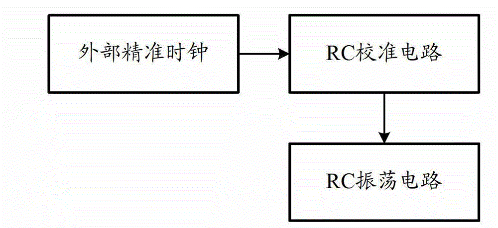
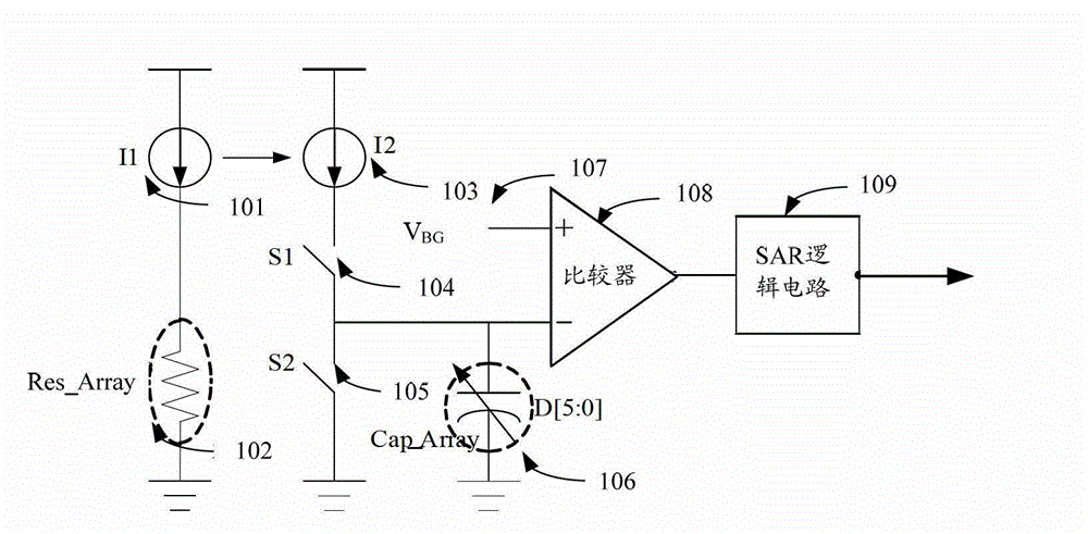
[0030] The first embodiment of the present invention relates to a circuit for providing a precise low-frequency clock signal. figure 1 It is a schematic diagram of the structure of the circuit that provides a precise low-frequency clock signal. Such as figure 1 As shown, the circuit that provides a precise low-frequency clock signal includes an ...


PUM


Abstract

The invention relates to the field of electronic communication, and discloses a circuit for supplying a precise low-frequency clock signal, and a control method for the circuit. The circuit for supplying the precise low-frequency clock signal comprises an external precise clock and a resistance and capacitance (RC) oscillation circuit and an RC calibration circuit which are manufactured in the same chip, wherein the RC calibration circuit executes calibration according to the external precise clock and a successive approsimation register (SAR) logic and obtains a fixed RC constant; and a produced calibration code for controlling a capacitor array can adjust the capacitor array of the RC oscillation circuit in the same chip, so that the RC oscillation circuit outputs the low-frequency precision clock which is simple and effective. After the RC oscillation circuit finishes circuit calibration, the external high-frequency precise clock and the RC calibration circuit can be switched off, so that power consumption can be greatly reduced.

Description

technical field [0001] The invention relates to the field of electronic communication, in particular to communication circuit design technology. Background technique [0002] The low-frequency precise clock can be applied in Micro Controller Unit (Micro Controller Unit, referred to as "MCU") state storage, data storage and watch dog circuits. However, there will be deviations in the manufacturing process of the chip in the complementary metal-oxide semiconductor (Complementary Metal-Oxide Semiconductor, "CMOS") process, which will cause a certain deviation in the value of the resistance and capacitance, and due to environmental temperature, humidity, pressure and other factors , the values ​​of resistors and capacitors will also be affected. Therefore, a circuit that depends on the RC constant will not meet the specification requirements due to the deviation of the RC constant by as much as 60%. [0003] RC calibration technology is common in the design of integrated circu...

Claims


Application Information

Patent Timeline
Patent Type & Authority Applications(China)
IPC IPC(8): H03K3/011
Inventor 栗成智马侠韩世英
Owner HI TREND TECH SHANGHAI
Learn More